-

Techniques for Calculating Relay Protection Settings
Use this Protection Relay Setting Calculator to calculate pickup current, time multiplier settings (TMS), operating time, coordination time interval (CTI), and plug setting multiplier (PSM) using fault current, CT ratio, and IEC 60255 curve parameters. For thermal overload protection (ANSI Device 49), the pickup is typically set at 115% to 125% of motor full-load amps depending on service factor. For overcurrent. This technical report refers to the electrical protections of all 132kV switchgear. All calculations are based on the available documentation/ information. These settings may be revaluated during the commissioning, according to actual and/or measured values. Presented at the 51st Annual Minnesota Power Systems Conference Saint Paul.
-
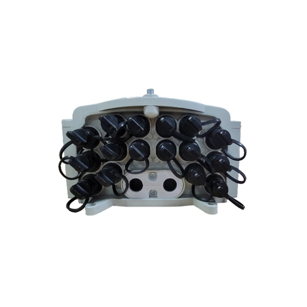
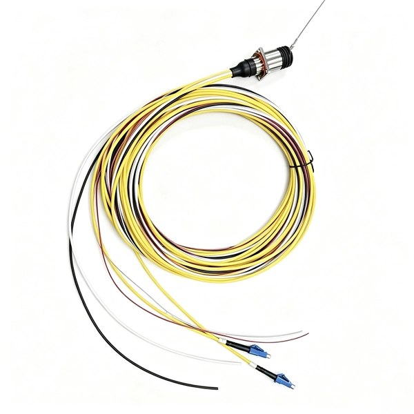
8-core optical cable splicing techniques
In this guide, we'll walk you through the entire process of preparing fiber optic cable for splicing and termination to fiber connectors. We'll explore the necessary tools, safety precautions, and step-by-step procedures for cable connectors, mechanical and fusion splicing methods. What is Fiber Optic Splicing and Why is it Needed? – #1. For network managers and technicians, a poor splice can lead to significant signal degradation, network downtime, and costly troubleshooting. 1dB for fusion) and degrade over time in outdoor environments. A professional splice kit includes: Every splice starts with proper preparation: clean the work area, protect against wind, and. Fiber optic splicing is the process of joining two fiber optic cables together so that light signals can pass with minimal loss or reflection. Splicing is typically required during cable installation, maintenance, or network expansion.
[PDF Version]
-
Protection level of busbar connectors
The International Electrotechnical Commission (IEC) sets out standardized testing procedures and benchmarks to ensure that busbar contact resistance remains within safe and acceptable limits. IEC standards are developed through international consensus and are used globally. The integrity of busbar joints is critical because. Busbars in power systems are the location where transmission lines, generation sources, and distribution loads converge. Because of this convergence, short circuits located on or near the busbar tend to have very high magnitude currents. The high magnitude fault currents require high-speed. Industry data shows that loose or improperly torqued busbar connections account for a significant percentage of electrical panel failures. Busbar distribution ensures these requirements are fully met. Performance criteria of. DEFINITIONS.
[PDF Version]
-
Six-Column Relay Protection Tester
Specifically designed for settings-based protection testing with a high degree of automation, our modular software Test Universe offers numerous functions and application-optimized test modules that save yo.
-
Several characteristics of relay protection are
To provide effective and reliable protection to the power system, a protective relay must have the following essential functional characteristics: Selective, Fast, Stable, Reliability, Sensitivity, Simple Construction and Installation Mechanism, and Cost-effective. A protective relay is an electrical switch which can automatically operate when a fault or any other abnormal conditions occur in the electrical system. It sends a signal to turn on the alarm or indicator or trip a circuit breaker to separate the faulty part from the healthy section. : 4 The first protective relays were electromagnetic devices, relying on coils operating on moving parts to provide detection of abnormal operating conditions such as. A protective relay is an intelligent electrical device designed to detect faults in power systems and initiate corrective actions such as tripping a circuit breaker. PSM – Plug Setting Multiplier (Current Setting Multiplier) What is PSM? 2).
[PDF Version]
-

Relay Protection Test Wiring Method
One approach to test the total protection system is to use primary injection techniques (see appendix H) that trigger protective relays and lockout relay, trip circuit breakers, and initiate annunciations and indications. If applicable, documentation is required detailing how verified protection segments overlap to ensure there is not a gap. The purpose of this Standard Work Practice (SWP) is to standardise and describe the method for testing of Ergon Energy protection relays for commissioning purposes. This SWP should be interpreted in conjunction with Standard for Substation Protection (V1. From a technician's perspective, master the unique skill of testing protection. When the transformer wiring type is Y/Y (Y0), the test wiring is very simple: when testing phase A, the tester IA is connected to the phase A of the high voltage side, and the tester IB is connected to the phase a of the low voltage side. After the neutral line of the high and low voltage sides is. Function: Use electronic components like transistors to perform switching. Applications: Frequency, undervoltage, and overcurrent protection.
[PDF Version]
-

Circuit Breaker Relay Protection Equipment Model
Microprocessor-based solid-state digital protection relays now emulate the original devices, as well as providing types of protection and supervision impractical with electromechanical relays.OverviewIn, a protective relay is a device designed to trip a when a is detected. The first protective relays were electromagnetic devices, relying on coils operating on moving par. Electromechanical protective relays operate by either, or. Unlike switching type electromechanical with fixed and usually ill-defined operating voltage thresholds. Electromechanical relays can be classified into several different types as follows: "Armature"-type relays have a pivoted lever supported on a hinge or knife-edge pivot, which carries a moving contact. These relays may.