-
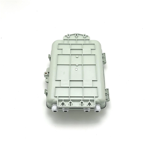
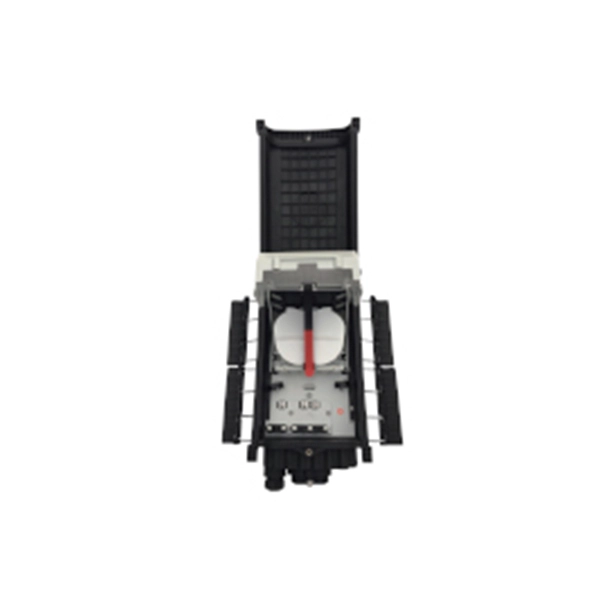
Is it okay to pick up the beam splitter outside
A beam splitter or beamsplitter is an optical device that splits a beam of light into a transmitted and a reflected beam. It is a crucial part of many optical experimental and measurement systems, such as interferometers, also finding widespread application in fibre optic telecommunications. DesignsIn its most common form, a cube, a beam splitter is made from two triangular glass which are glued together at their. Beam splitters are sometimes used to recombine beams of light, as in a. In this case there are two incoming beams, and potentially two outgoing beams. But the amplitudes. For beam splitters with two incoming beams, using a classical, lossless beam splitter with Ea and Eb each incident at one of the inputs, the two output fields Ec and Ed are linearly related to the inputs thro. Beam splitters have been used in both and in the area of and and other fields of. These include: •. In quantum mechanics, the electric fields are operators as explained by and. Each electrical field operator can further be expressed in terms of representing the wave behavior a.
[PDF Version]
-

Principles and Product Design of Optical Fiber Communication
Optical Fiber Communication (OFC) revolutionizes modern telecommunications, enabling rapid data transfer across long distances with minimal signal loss. This comprehensive review explores OFC's historical evolution, core principles, components, and versatile applications. Kanade Department of Electronic-Science, P. College of ASC, Pravaranagar, India fPublished. The digital communication techniques discussed so far have led to the advancement in the study of both Optical and Satellite communications. Light acts as a carrier wave and can be modulated to carry information. Higher bandwidth (extremely high data transfer rate).
-
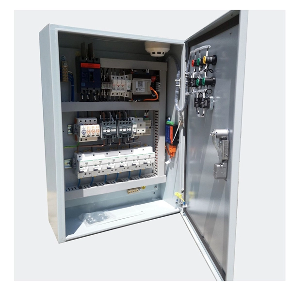
Requirements for Relay Protection Design
The IEEE standard for protection relays refers to a collection of guidelines developed by the Institute of Electrical and Electronics Engineers. This document provides recommendations, background and philosophy on relay protection that is not available in M07. They are intended to quickly identify a fault and isolate it so the balance of the system continue to run under normal conditions. For professionals working in utilities, industries, or renewable energy systems, understanding these standards is not optional—it is essential. This handbook covers the code of practice in protection circuitry including standard lead and device numbers, mode of connections at terminal strips, colour codes in multicore cables, dos and donts in execution.
-

WDM Fiber Optic Communication System Design
This lesson demonstrates the basic features of a typical WDM optical communication system and shows the basic design steps with OptiSystem. The performance of the system will be shown and compared. In fiber-optic communications, wavelength-division multiplexing (WDM) is a technology which multiplexes a number of optical carrier signals onto a single optical fiber by using different wavelengths (i. Single mode fiber is favored over Multimode fiber for long-distance communication. Firstly, the WDM optical. While fiberoptic technology resulted in a significant increase in a network's "bandwidth," or the amount of information that the network could send, tbe creation of the Internet resulted in an even greater demand for bandwidth. As demand for network capacity increased, service providers exhausted.
-
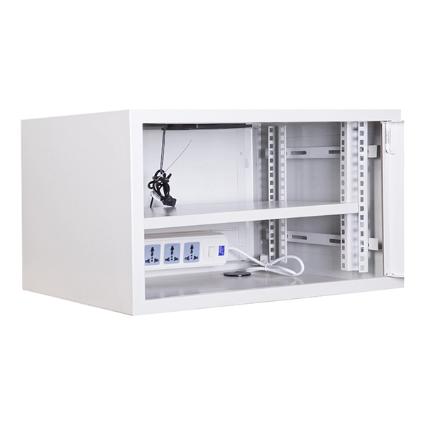
Can grounding be done outside the distribution box
As for your title question: yes, it's sufficient to ground an outlet only to its box -- if, and only if, the box itself is properly grounded. Metal boxes are grounded whenCorrect grounding of services depends upon understanding the definition and role of the grounded conductor. The neutral conductor is typically the grounded conductor connected to the system's neutral point, carrying current under normal operation. Grounding electrode conductors must be connected at. Today, we're diving deep into the world of distribution box grounding, breaking down the standards, and shining a light on those sneaky mistakes that even experienced electricians sometimes make. Code Change Summary: Clarifications were made regarding the connection of equipment grounding conductors in a box. Why was this so common? What the the thinking in doing it this way? This is. For one thing, the conductors are passing through box mounting holes! That particular kind of conductor belongs in conduit, which should be entering through one of the circular knock-out holes in the box. Check your local electrical codes and schedule inspections.
[PDF Version]
-
Power Plant Dual Relay Protection Configuration Standards
IEEE Std 242 - 2001 IEEE Buff Book–IEEE Recommended Practice for Protection and Coordination of Industrial and Commercial Power Systems IEEE Std C37. 95-2002 (R2007)Power System Protective Relays: Principles & Practices Protective Relays - Technical Seminar Nov 2016 - Copyright: IEEE 1 Power System Protective Relays: Principles & Practices Presenter: Rasheek Rifaat, P. Eng, IEEE Life Fellow IEEE/IAS/I&CPSD Protection & Coordination WG Chair Jacobs Canada. This document supplements PJM Manual 07 which contains the minimum design standards and requirements for the protection systems associated with the bulk power facilities within PJM. This document provides recommendations, background and philosophy on relay protection that is not available in M07. Consideration is given to availability and location of breakers, current sensing devices, and disconnect switches, as well as bus-switching scenarios, and their impact on the selection and application of bus protection. Its modular design and powerful DIGSI 5 engineering tool provide tailored solutions. You will get a list of all suitable products!.
[PDF Version]