-
Fiber optic sensor affected by light
Fiber optic current sensors work by detecting changes in light as it interacts with a magnetic field created by an electrical current. These sensors rely on the Faraday Effect, which occurs when a magnetic field causes a rotation in the polarization of light passing through an. A fiber optic sensor is a measurement device that uses light traveling through a glass or plastic filament to determine a physical quantity such as temperature, pressure, or strain. The optical. A Fiber Sensor is a type of Photoelectric Sensor that enables detection of objects in narrow locations by transmitting light from a Fiber Amplifier Unit with a Fiber Unit. These sensors are available at less cost, in small size. The Fotonic Sensor transmits a beam of light through a flexible fiber-optic probe, receives light reflected from a target surface, and converts this light into an electrical signal proportional to the distance between the probe tip and the target being measured. A simplified example of the fiber.
[PDF Version]
-

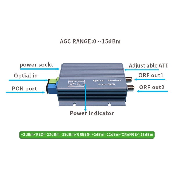
Fiber optic sensor readings decrease
Use High-Quality Fiber: Choose ITU-T G. A1/B3 fibers for lower attenuation and better bend tolerance. Minimize Connections: Plan your links to use as few connectors and splices as possible. Clean Connections Religiously: A dirty connector is the #1 cause of unexpected. Fiber Optic Measurement Units: "dB" and "dBm" Whenever tests are performed on fiber optic networks, the results are displayed on a power meter, OLTS or OTDR readout in units of “dB. ” Optical loss is measured in “dB” which is a relative measurement, while absolute optical power is measured in “dBm,”. Fiber optic signal loss, also known as attenuation, occurs when optical signals weaken as they travel through the fiber. Use. The most common symptom of signal loss is a decrease in network performance. Slower connection speeds, increased latency, and packet loss are all telltale signs that something might be amiss with your fiber optic cables. Regular monitoring of these metrics can help preemptively identify and address. Problems within a fiber link can occur due to a wide variety of reasons.
[PDF Version]
-
Positioning using a through-beam fiber optic sensor
Fiber optic position sensors utilize light transmitted through optical fibers to determine the position or displacement of an object. All information about the E20827 at a glance. We assist you with your requirements. ✓ Technical data ✓ Mounting and Installation Instructions ✓ CAD drawings ✓ Compatible Accessories There are several types of fiber optic sensors. Detection methods include thrubeam, reflective, retro-reflective, and definite-reflective. As the target. Through-beam sensors from Balluff serve to detect objects reliably, regardless of surface, color, material - even with a heavy gloss finish.
-
Function of Magnetic Ring Fiber Optic Sensor
In this paper, based on a ring-shaped structure, an intensity demodulation fiber-optic sensor is explored and experimental verified. The Higher Educational Key Laboratory for Flexible Manufacturing Equipment Integration of Fujian Province, Xiamen Institute of Technology, Xiamen 361021, China The State Key Laboratory for Mechanical Manufacturing Systems Engineering, Xi'an Jiaotong University, Xi'an 710054, China Shandong. Here we propose a high-resolution fiber ring magnetometer based on laser frequency stabilization technology. By connecting one output port to an input port of a fiber coupler with a splitting ratio of 1:99, the fiber ring resonator (FRR) generates a series of highly narrow transmission resonances. A magnetic field sensing system based on a phase-shift fiber loop ring-down (FLRD) technique and multi-mode interferometer (MI) coated with magnetic fluid (MF) is proposed and demonstrated. A sensitivity of 1306 pm/mT was experimentally demonstrated in the range of magnetic fields from 0 to 15 mT.
[PDF Version]
-
Fiber Optic Splice Installation and Removal Method
In this guide, we'll walk you through the entire process of preparing fiber optic cable for splicing and termination to fiber connectors. We'll explore the necessary tools, safety precautions, and step-by-step procedures for cable connectors, mechanical and fusion. A fiber optic cable splice is the process of permanently joining two fiber optic cables to create a continuous light path—vital when cables are cut, damaged, or need extending. This blog gets into the intricacies of these components, offering insights into their types, installation processes, maintenance, and more. What. What is Splicing and When Would You Want to Splice Fiber Optic Cables? First, let us understand the meaning of the term “splice. They protect and organize the sensitive connection points between optical fibres and play a decisive role in the quality, reliability and ease of maintenance of the entire network.
[PDF Version]
-

Fiber optic sensor adjusts intensity
A fiber optic sensor measures a physical quantity by modulating the intensity, spectrum, phase, or polarization of light traveling through the optical fiber system. It's a device that converts light rays into electronic signals. Think of it like a photoresistor, which changes its resistance based. Abstract—This article presents a novel approach to physical-displacement-based power grid measuring via an intensity-modulated fiber-optic sensor (IMFOS).