-
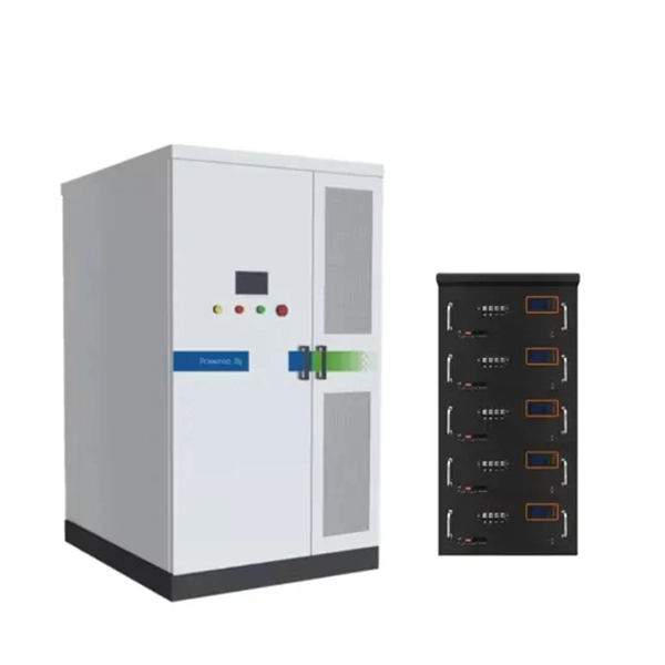
Egypt Solution ONU Optical Network Unit PAM4
A physical-layer network coding (PNC) based inter-ONU-communication (IOC) scheme is proposed for next generation high-speed PONs which apply four-level pulse amplitude modulation (PAM4). A 25 Gb/s f.
-

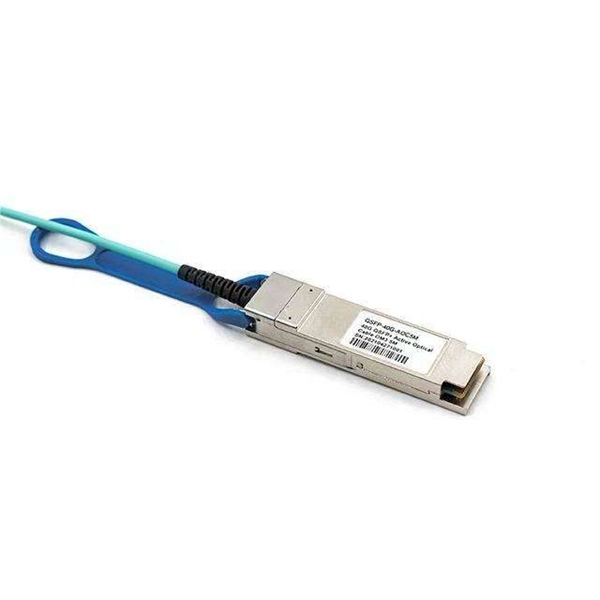
Syrian PAM4 optical transmitter
The system in this example contains the following elements: 1. 2 Pseudo-random Bit Stream (PRBS) block 2. 2 NRZ Pulse Generator (NRZ) 3. 1 CW Laser (CWL) 4. 3 1x2 Fork (FORK) 5. 2 Electrical Not Gate (N.
-
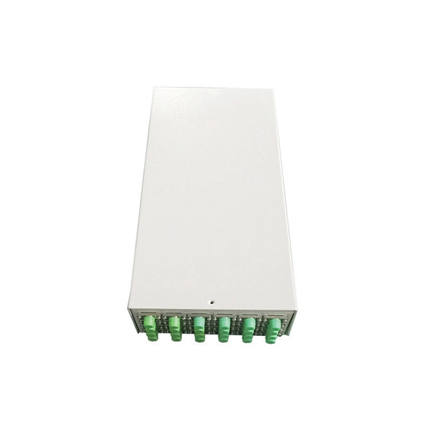
Congo OEM optical transmitter PAM4
The system in this example contains the following elements: 1. 2 Pseudo-random Bit Stream (PRBS) block 2. 2 NRZ Pulse Generator (NRZ) 3. 1 CW Laser (CWL) 4. 3 1x2 Fork (FORK) 5. 2 Electrical Not Gate (N.
-
Should the cable management rack be installed in the front or the back
Leave space for cable management —especially in the back. Ensure front-to-back airflow by leaving gaps or using filler panels. This method helps maintain neatness and accessibility within the rack while ensuring efficient airflow and ease of maintenance. Both overhead and under floor pathways should be designed to support the weight of cables in the initial installation and it should also facilitate the addition of future cables. With proper design and structured tools, it helps organize cables, ensure stable signal transmission, simplify maintenance, and improve overall system. Here are some best practices for rack placement: Implementing hot and cold aisle containment is a fundamental strategy for improving airflow and cooling efficiency. The racks should be positioned in a way that optimizes.
-
Key Points for Relay Protection Operation
Relay protection is the discipline of designing schemes that detect faults, coordinate relays, and isolate equipment without outages. While this is bad, It's not a. The potential transformers (PTs) and current transformers (CTs) usually produce electrical signals which monitor the state of current and voltage in a system. CTs and PTs reduce the high currents and voltages of a power system to those levels which can be handled by a relay safely. It emphasizes selectivity, coordination, fault response, and system behavior rather than individual relay devices.
-
Fixing bracket on the back of the distribution box
How to install the mounting bracket? Many engineers don't know how to install this accessory. With the latest design, it can be confusing. Mounting bracket is a flexible structure, which makes it easy to adjust or replace the electrical components. All the components, wires and connections are under the protective cover due to the same height. The BBT-HF telescoping bracket, used with the BBA and BBA-4 box mounting brackets, provides an extremely flexible, fast rough-in solution. more Charlie DIYte (CharlieDIYte) tagged products below. Make sure the walls are strong enough to bear the weight of the box and electrical equipment. Ground. Electrical box screw mounts broke, can it be fixed without tearing up wall? I was unplugging an appliance in the kitchen when the whole outlet pulled out of the wall. Second photo shows my temp.