-
What are the components of an optical guide driver module
The optical module is usually composed of Transmitter Optical Subassembly (TOSA, containing a laser LD Chip), Receiver Optical Subassembly (ROSA, containing a photodetector PD Chip), a driving circuit, and an optical and electrical interface. Its schematic is shown in Figure 1. The internal structure of an optical module is complex but can be divided into several main parts. It is the core device for connecting communication equipment with optical fibers. Operating at the physical layer of the OSI model, optical modules are core devices in optical. As an important part of fiber-optic communication, an optical module is a photoelectric converter which converts electrical signals into optical signals and vice versa. Composition of Optical Modules The optical module, known as Optical Transceiver in. The optical module serves as a crucial component in optical fiber communication systems, operating at the physical layer, which is the lowest layer in the OSI model.
[PDF Version]
-
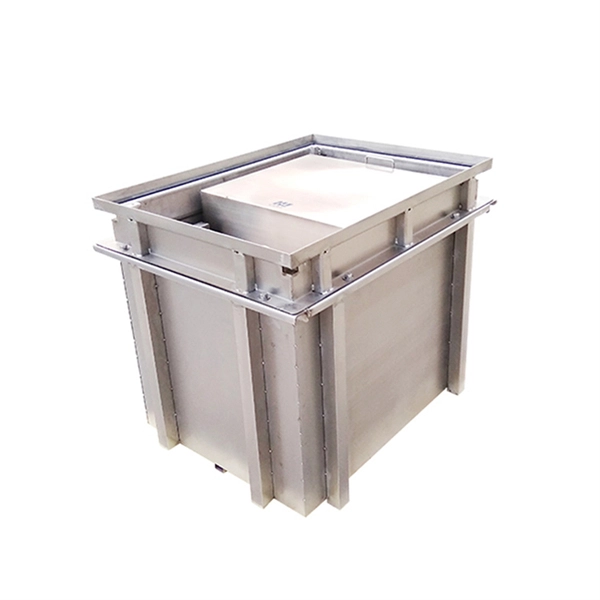
Heating components in optical cable factory
Induction heating is commonly used in wires, cable, and optical fiber manufacturing. Another application of the induction heating for this industry is heating of a susceptor to melt special glass and draw. The optical communications cable includes a cable body having a first end, a second end, an outer surface, an inner surface and a channel defined by the inner surface and extending between the first end and the second end. What are Fiber heaters used for? Tapering, fiber couplers, selective heating, and joining. (FOA) was founded in 1995 to help develop the workforce to build the fiber optic networks to support a rapid expansion in communications and the Internet. The charter of the FOA was to promote professionalism in fiber optics through education, certification, and. The accuracy, control and efficiency of induction heating makes it ideal for many key tasks in the manufacture and processing of wire and cable products.
[PDF Version]
-
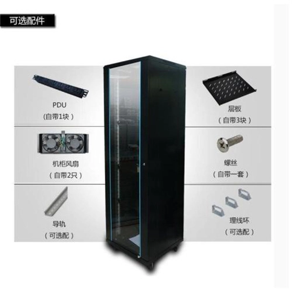
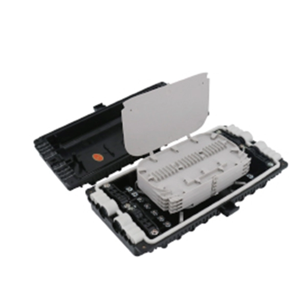
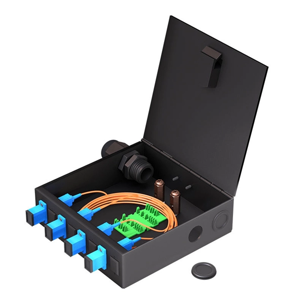
What are the main components of an optical distribution box
ODF, also known as optical distribution frame or fiber optic patch panel, is a critical device used in optical communication for managing and distributing optical fibers. They provide efficient fiber optic management, connectivity, and protection. It is usually a compact and structured framework composed of a steel shell and internal fiber splice tray as the main. This complete guide explores everything you need to know about ODFs — from their structure, types, and key components, to installation best practices and modern design trends. Whether you're building a central office, data center, or FTTx distribution network, understanding the right ODF.
-
Components of Passive Optical Networks
A passive optical network consists of an optical line terminal (OLT) at the service provider's central office (hub), passive (non-power-consuming) optical splitters, and a number of optical network units (ONUs) or optical network terminals (ONTs), which are near end users. A passive optical network (PON) is a fiber-optic telecommunications network that uses only unpowered devices to carry signals, as opposed to electronic equipment. In practice, PONs are typically used for the last mile between Internet service providers (ISP) and their customers. In essence, a PON is a fiber-optic system that delivers data from a single source to multiple endpoints using only. A passive optical LAN, called POL or POLAN, is short for Passive Optical Local Area Network.
-
The function of a 10 Gigabit optical splitter
By dividing a single optical signal from a central Optical Line Terminal (OLT) into multiple outputs for Optical Network Terminals (ONTs) at users' homes, splitters eliminate the need for dedicated fibers to each residence—slashing infrastructure costs while scaling network reach. An Optical Splitter, also known as a beam splitter, is a passive optical device that divides a single input optical signal into two or more output signals. Conversely, it can also combine multiple signals into one. Optical splitter. Where splitters are placed in the network can make significant impacts on fiber counts, network cost and deployment time and operational steps, such as customer onboarding and maintenance. One important note is that splitting architectures should be seen as tools that can be mixed and matched to. The trick is how that single signal gets divided. That's where splitters come in.
[PDF Version]
-
Hazards of Laying Optical Cables
Optical fibers, though renowned for their efficiency and bandwidth, aren't immune to risk factors that could spawn safety hazards. The very nature of fiber optic cabling requires handling microscopic strands that, when damaged, can cause signal loss or, worse, physical harm. Understanding the safety hazards that go with fiber optic cable is critical for those who install or maintain fiber optic systems. As electrical professionals, most of us take fiber optic (FO) safety for granted. Recognizing the potential safety hazard inherent in the installation and maintenance of optical fibers is crucial to mitigating risks of personal or property damage. Know the standards that apply to your work Whether you're installing new fiber optic cables or troubleshooting and repairing an existing fiber network, a working knowledge of the regulations that apply to your. However, fiber optics installation is not without risks. Even the output of OTDRs, WDM and fiber amplifier systems, which are. Working with fiber optic cabling requires precision, skill, and a strong understanding of cabling safety.
[PDF Version]
-
How are optical power meters classified
An optical power meter (OPM) is a device used to measure the power in an signal. The term usually refers to a device for testing average power in systems. Other general purpose light power measuring devices are usually called,, power meters (can be sensors or ), or lux meters. A typical optical power meter consists of a , measuring and display. The sens.
-
What is the appropriate height for optical fiber cables
Based on my first-hand, environmental testing of the declination of the ceramics under pressure and under temperature, I recommend targeting a fiber height of +/-20 nanometers. The Fiber Optic Association, Inc. (FOA) was founded in 1995 to help develop the workforce to build the fiber optic networks to support a rapid expansion in communications and the Internet. The charter of the FOA was to promote professionalism in fiber optics through education, certification, and. Fiber height is a critical geometry parameter (along with Radius, Angle/Apex, and Key Error), which directly impacts the optical performance of the connector in the fiber optic network. Failure to follow these guidelines may result in damage or attenuation increases of the optical fiber or cable. Proper industry. cations, security, control and similar purposes. FO-VC2 JOINT USE - VERICAL MIDSPAN CLEARANCES 48.
[PDF Version]
-
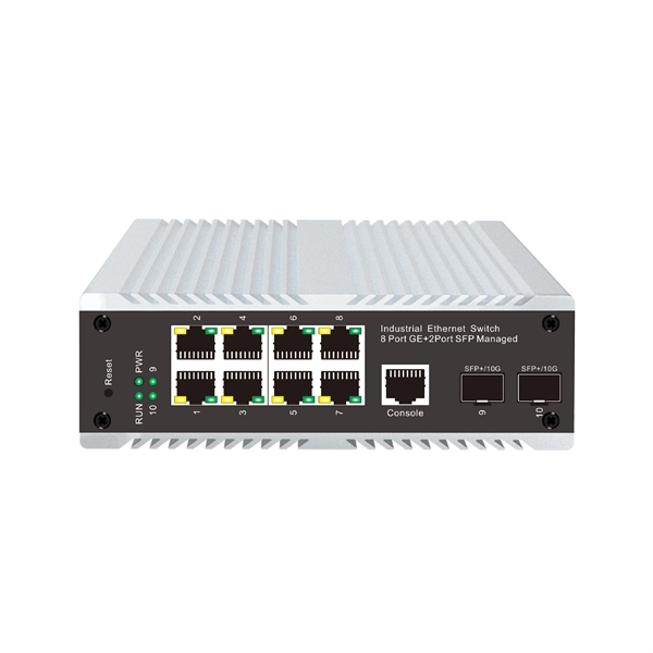
10 Gigabit Ethernet card optical module not connected to fiber optic cable
Troubleshooting SFP+ link issues in 10 GbE networks requires attention to module type, match of speed and wavelength, clean fiber connections, correct configuration, thermal management, and equipment compatibility. You can quickly resolve SFP+ Module connectivity issues by following a systematic optical transceivers troubleshooting process. Check for common connection problems, such as link failures or modules not recognized. Check compatibility between the optical module and switch Most switch brands have specific compatibility requirements. During network upgrades, many enterprise users encounter a common issue: after replacing 10G broadband lines or inserting 10G SFP+ optical modules, the switch still fails to operate at full 10G bandwidth or even fails to recognize the modules. We've listed the five most common ones. First of all, let's briefly recap what SFP and SFP+ stand for. SFPs – short for 'small form-factor pluggable' – are compact, hot-pluggable devices.
[PDF Version]
-
Switches are all 10 Gigabit optical
To implement different 10GbE physical layer standards, many interfaces consist of a standard socket into which different physical (PHY) layer modules may be plugged. PHY modules are not specified in an official standards body but by (MSAs) that can be negotiated more quickly. Relevant MSAs for 10GbE include (and related X2 and XPAK), and. When choosing a PHY.