-
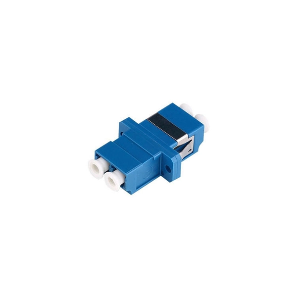
How are optical power meters classified
An optical power meter (OPM) is a device used to measure the power in an signal. The term usually refers to a device for testing average power in systems. Other general purpose light power measuring devices are usually called,, power meters (can be sensors or ), or lux meters. A typical optical power meter consists of a , measuring and display. The sens.
-
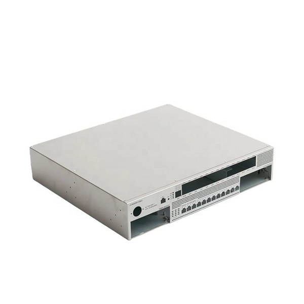
Normal optical power of the switch
Transmit power is typically good when it is in the 6 dB range between -1 and -7 dBm. Have you ever encountered a Cisco switch interface that constantly flaps (goes up and down) or suddenly enters an err-disabled state? Before you blame the switch or replace the cable, you need to look at the invisible data: the light levels. If either Tx or Rx is in the -30 dBm or lower range that's usually indicative of there being no actual signal received and the transceiver is reporting. When designing optical networks, understanding the TX/RX power range is vital for ensuring optimal performance and long-term reliability. All ports below are 10gbps 850nm sm. See the one for port 2:59 has a * (star) next to RxPower. The reliability of this transmission depends entirely on the strength of that light signal as it reaches its destination.
-
What frequency should the optical power meter be selected for
The frequency detected by an optical power meter typically refers to the frequency of a modulated test tone used for fiber identification and continuity testing, not a property of the meter itself. These test tones are commonly 270 Hz, 1 kHz, or 2 kHz. TIA standard test FOTP-95 covers the measurement of optical power. We'll give you the basic information you need and provide some printable references. This article provides a comprehensive. This guide is written to equip readers with the power meter selection know-how necessary for making sound decisions regarding purchasing these devices. The guide identifies models' primary functional features, explains the most crucial parts of their specifications, and assesses their operational.
-

Optical module test power not adjusted too low
What does it mean if the transmitted power is too low? Low transmitted power can mean the connectors are dirty. Clean the connectors, check the module, and look at the fiber. If it still does not. Stable optical power is the foundation of every high-capacity optical transport system. Even minor deviations—whether too high, too low, or unstable—can impact signal integrity, trigger service alarms, or interrupt traffic on DWDM, OTN, or long-haul optical line systems. Because optical networks. The article Digital Diagnostic Function (DDM) For Optical Modules describes that DDM function can be used for real-time monitoring and fault location of the module's working status, in which the optical module's transmitting optical power and receiving optical power are the key parameters for. To test transmitted power in sfp optical modules, you use an optical power meter to get exact results. Many sfp modules also have DOM/DDM, which lets you see digital diagnostic monitoring data on network equipment. Built into modern SFP/SFP+/ SFP28 /QSFP family modules and standardized by SFF-8472, DDM/DOM exposes real-time values for the module's temperature, supply.
[PDF Version]
-
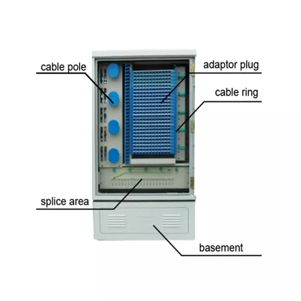
Power Engineering OPGW Optical Cable
An optical ground wire (also known as an OPGW or, in the IEEE standard, an optical fiber composite overhead ground wire) is a type of cable that is used in overhead power lines. Such cable combines the functions of grounding and telecommunications. An OPGW cable contains a tubular structure with one or more optical fibers in it, surrounded by layers of steel and aluminum wire. The. HistoryAn OPGW cable was patented by BICC in 1977 and installation of optical ground wires became widespread starting in the 1980s. In the peak year of 2000, around 60,000 km of OPGW was installed worldwide. Asia, especially. Several different styles of OPGW are made. In one type, between 8 and 48 glass optical fibers are placed in a plastic tube. The tube is inserted into a stainless steel, aluminum, or aluminum-coated steel tube, with some slack lengt. Optical fibers are used by utilities as an alternative to private point-to-point microwave systems, or communication circuits on metallic cables. OPGW as a communication medium has some adva.
[PDF Version]
-
Equipment parameters of optical power meter
Fiber optic power meters measure the average optical power out of an optical fiber. Power meters typically consist of a solid state detector (silicon for short wavelength systems, germanium or InGaAs for long wavelength systems), signal conditioning circuitry and a digital display of. An optical power meter (OPM) is a device used to measure the power in an optical signal. In this article, learn: What is an optical power meter? An optical power meter (OPM) measures the power levels of light signals in devices that transmit data or power using. Testing fiber optic components and cable plants requires making several measurements with the most common measurement parameters listed in the Table below. To augment the absolute power measurements NIST provides nonlinearity, spectral responsivity, and uniformity measurements.
-
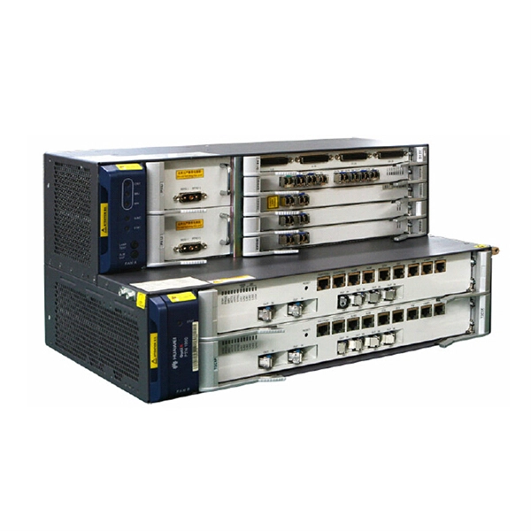
Power of Huawei optical modules
In the AI era, Huawei provides a full range of GE to 800GE optical modules, featuring three major capabilities: Spanning (ultra-long transmission), Stable (ultra-high reliability), and Secure (ultra-solid security). To address these demands, Huawei has launched the StarryLink optical module brand. This announcement occurred during the data center session titled. Describes what an optical module is and FAQs, including the fundamentals, appearance and structure, key performance counters, common types, and naming conventions of optical modules, causes of optical module failures and corresponding protection measures, types of optical modules supported by. An optical module is a component that completes electrical/optical conversion on an optical network. Huawei MA5600T series only support GPON and XG-PON; MA5800 series supports GPON, XG-PON, XGS-PON, XG-PON&GPON Combo, XGS-PON&GPON.
[PDF Version]
-
How to determine light attenuation of red light using an optical power meter
Optical attenuation compares input and output power on a logarithmic scale. When powers are in linear units, the loss in decibels is: Attenuation (dB) = 10 × log10 (Pin / Pout) If the link length L is provided, the attenuation coefficient is: Coefficient (dB/km) =. Analyze optical power drop across fibers and links. Switch units, lengths, and calculation modes easily. Needed when attenuation is an. Optical power, required for measuring source power, receiver power and, when used with a test source, loss or attenuation, is the most important parameter and is required for almost every fiber optic test. Backscatter and wavelength measurements are the next most important and bandwidth or. Optical power meters are a key element in the optimization and maintenance of such optical networks and of their components. But, for designers, just starting to work in the fiber-optic design space, measuring attenuation can seem like a monumental task.
[PDF Version]