-
Methods for measuring optocouplers using a multimeter
Testing the functionality of an optocoupler with a multimeter is critical for electronics enthusiasts and professionals. From basic circuit design to complex industrial systems, accurate optocoupler. Optocoupler is one type of ICs, It isolates input and output section by using optical technology this feature increase safety of circuit. Optocoupler has many part number, different part number has different output type so before checking it has to use part number to research with datasheet and. Testing for failure with a multimeter is only partially effective, whereas a dedicated optocoupler testing circuit provides clear results in just seconds. For related tutorials and step-by-step build guides, explore Circuit Digest's Electronic Circuits hub. Design considerations, including adequate spacing on PCBs for insulation, must be followed to ensure performance remains reliable and safe.
[PDF Version]
-
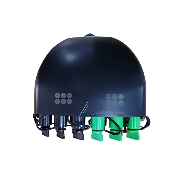
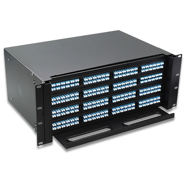
FTTR Information Panel IK10 After-Sales Service Specifications and Models
Model number: CSR101GG190-V2. Application: Smart control, Medical equipment, Industrial control, etc 3. Structure: Glass Lens + ITO glass sensor+FPC 4. Touch type: Multi touch (can be customized) 5. Certificates: Reach, RoHS, ISO9001Page 1 Symbols Used in This Manual DANGER Failure to follow these instructions identified by this symbol could result in death or serious injury to you and/or other people. This is the official maintenance and repair manual used at service stations and authorized dealerships. This comprehensive manual provides detailed information, procedures, and guidelines for maintenance, repairs, and troubleshooting. An IK10 touch screen is designed to withstand severe mechanical impact in industrial and public environments where reliability and durability are critical.
-

Calibrating a multimeter in Uganda
Now that you have connected the digital multimeter calibration standard, you are ready to start calibrating your multimeter. The process of calibrating a digital multimeter is relatively easy. To calibrate your m.
-
How to test a photovoltaic panel with a multimeter
Testing solar panels is easy with a multimeter! To test the current, simply connect the multimeter to the panel's output. Whether you're a seasoned solar enthusiast or a newcomer to the world of renewable energy, knowing how to use a multimeter to test your solar panels is a valuable skill that can empower you to take control of your energy production. Measure Voc (open circuit voltage) — if it reads 0V, the panel or wiring is dead. If Voc is normal but the system is not producing, the problem is downstream. Solar panels are usually tested under standard conditions using a light source that mimics the light from the sun on a clear day. This helps you spot issues early and keep your system running efficiently.
-
How to use a 1500V photovoltaic multimeter
Connect the positive lead of the multimeter to the positive terminal or wire of the solar panel. In the rapidly evolving solar industry, the shift from 1000V to 1500V DC systems has become the new standard for utility-scale projects. While this increases efficiency, it creates a dangerous gap in the toolkits of many technicians. Whether you're working with a utility-scale solar photovoltaic (PV) array, wind power, an electric railway, or a data center, the Fluke 283 FC has been. 🔋 Maximize the safety and performance of your solar PV system with the PV-ISOTEST 1500VDC insulation meter! Designed to meet IEC/EN62446 standards, this professional-grade tool allows for accurate insulation resistance testing, ground fault localization, and PV system verification.
-
Fiber Optic Fusion Splicer Calibration Time
Next the splicer prompts to confirm that a Quick Optimization or Arc Calibration has been performed before splicing the fiber. Fusion splicing is the process of fusing or welding two fibers together usually by an electric arc. The guide provides the complete workflow, covering safety precautions, tool selection, fiber preparation, fusion operation, quality control, and. Fusion splicers are essential for creating low-loss, high-performance fiber optic connections in telecom, FTTH, and data center applications. Top-rated models. It is recommended practice to keep fiber optic test equipment calibrated in measurement to ensure fast troubleshooting when locating network failures or when providing optical attenuation or optical cable length certification results. These records are required to close out a project and receive. At FiberOptic Resale our technicians have the experience and knowledge to clean and calibrate a broad range of fusion splicers and cleavers. Please follow all warnings and cautions for your safety and the protection of the equipment.
[PDF Version]