-

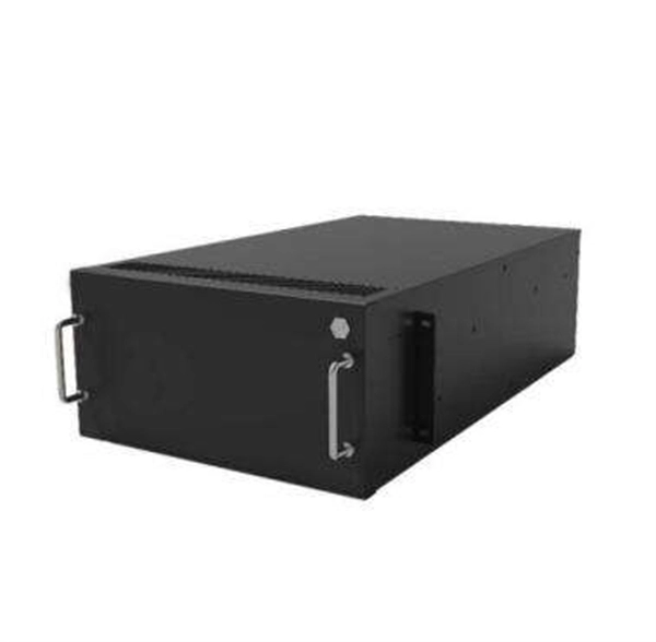
How to connect the SD signal in the 19 optical module
The unit accepts one SDI signal on a BNC connector and provides one optical output of this signal on an ST connector over single-mode cable with a 1310 nm wavelength. solution for virtually any conversion you could need. Mini Converters convert analog to digital, digital to analog, SDI to audio, audio to SDI, up, down and cross conversion, SDI distribution, and can even provide a sync generator for lockin all your video equipment to the same reference signal. These transceiver modules are hot-swappable input/output (I/O) devices that plug into 100BASE, 1000BASE and 10GBASE ports (for SFP+), which connect the module port with the fiber-optic or copper network. If the optical module is installed on a GE port, run the display interfaceGigabitEthernet x/x/x command to view port information when the optical module. When the optical module on an interface is faulty, you can run the display commands to view information about the optical module. The notices referring to your personal safety are highlighted in the manual by a safety alert symbol, notices referring only to property damage have no safety alert.
[PDF Version]
-
Optical module receiving sensitivity is less than
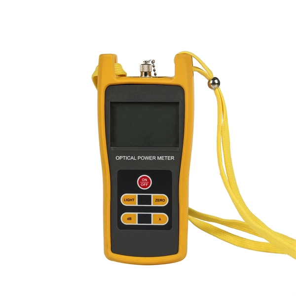
Receive sensitivity defines the minimum optical power required to maintain an acceptable bit error rate (BER ≤ 1E-12) at specific data rates. It's a core parameter in optical transceiver specifications, indicating the module's capability to detect weak incoming signals. What Is BER? The bit error rate (BER) measures the data transmission precision within. In optical communication systems, sensitivity is a measure of how weak an input signal can get before the bit-error ratio (BER) exceeds some specified number. For example, SONET specifies that the BER must be 10 -10 or better. This level must fall within the receiver's power range.
-
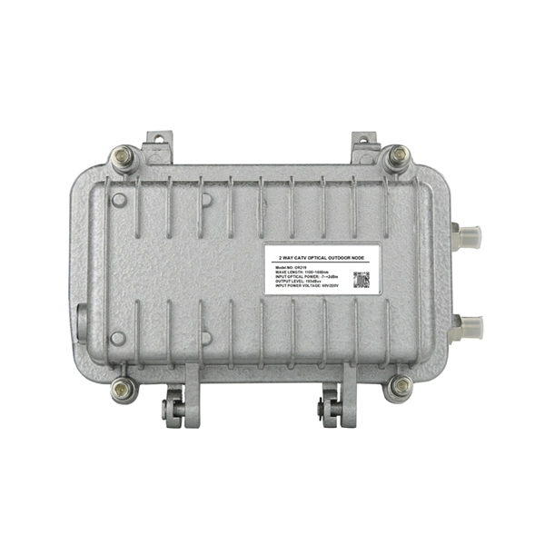
RRU optical module location
RS can be installed in a suitable machine room location, and RRU is installed at the antenna end. By separating RS from RRU, the tedious maintenance work can be simplified to the RS end. AAU, RRU, and BBU are key components in a telecom network, particularly in modern wireless communication systems like 4G and 5G. Here's a breakdown of each: The central processing unit in a base station. Usually. Optical modules used in Remote Radio Units (RRUs) for CPRI applications are required to support industrial temperature ranges, primarily because RRUs operate in diverse outdoor environments with extreme temperature variations. CPRI (Common Public Radio Interface) defines the interface relationship. RRU is short for remote radio unit. Strip the jacket off the RRU power cable for a small part, press the exposed shielding layer on the strap, and then connect the PGND cable on the strap to the nearest grounding bolt on the side in the. The mode. Determine a position for installing 2. Loosen the two M10 nuts on the mounting M10 bolt from the U notch.
[PDF Version]
-

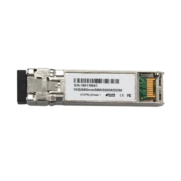
How to connect the 10 Gigabit Ethernet cable to the fiber-to-electrical port module
A special 10G Copper RJ-45 Transceiver (10G-SFP-T) is required to connect the SFP+ port to RJ45. It allows connecting a server/storage side Cat6/7 cable to an SFP+ port transceiver. An SFP module (or optical transceiver) converts electrical signals from network devices (switches, routers) into optical signals for fiber transmission and vice versa. 1G/10G SFP+: Standard for Gigabit and 10 Gigabit Ethernet. These transceiver modules are hot-swappable input/output (I/O) devices that plug into 100BASE, 1000BASE and 10GBASE ports (for SFP+), which connect the module port with the fiber-optic or copper network. 4ft (30m) * using Cat6a/Cat7 or above cable for 10G connection in various applications. In this video, we'll guide you through building a high-speed 10G LAN by connecting two fiber switches. Finally, check the transmit (TX) and receive (RX) paths to ensure that signals are aligned.
[PDF Version]
-

Huawei 5680 optical module emits light
The optical module is faulty. SmartAX MA5680T: Access product manuals, HedEx documents, product images and visio stencils. Get your solutions if you have met some problems. Explore the essential query commands for efficiently managing and troubleshooting the Huawei MA5680T, a versatile and robust telecommunications access platform. Learn how to retrieve vital information, configure settings, and diagnose network issues using these commands. Indicates the MIB object ID of the alarm. Does anyone have any troubleshooting suggestions for this device? Here's what I've checked so far: In case it matters, here are. Description: Original Huawei optical line terminal for FTTx networks, supporting GPON/EPON, IPTV, VoIP, and enterprise services. The Huawei OLT MA5680T is a large-capacity optical line terminal widely deployed in FTTx networks.
-

How to enable the optical module after plugging it into the optical port
Align the SFP module with the optical port and insert it horizontally, pressing firmly until the bottom of the module engages with the locking spring of the optical interface. Figure 1 SFP Optical Module Installation. The Cisco Small Business Series Switches allow you to plug in a Small Form-factor Pluggable (SFP) transceiver in their optical modules to connect fiber optic cables. Once the transceiver and fiber optic cable are plugged in properly in the switch optical module, you should be able to view the. This section describes how to install optical transceivers on the SFP or SFP+ ports and connect them to the ports of the peer device using optical fibers according to the network plan. The USG supports both 1 Gbit/s, 10 Gbit/s, and 40 Gbit/s optical modules. The LED will only light up when all connections are properly established and functioning correctly. The installation process can be taken by the following instructions.
[PDF Version]
-
Symptoms of optical module failure
This is typically due to one of the following failures: hardware defect, poor seating, or incompatibility. The result here is a down port with no data flow. This could be that the link dropped periodically or the link was unstable. This article will help you understand various warning signs for common faults, suggest practical troubleshooting steps, and share preventive inspections and maintenance, so you can do your. While generally reliable, failures do occur, leading to frustrating downtime, performance degradation, and costly troubleshooting. This guide. An optical module is a critical component in modern optical communication systems, directly affecting transmission stability, network reliability, and operational efficiency. However, during installation and daily operation, various issues may arise.
-
Epon optical module frequency band
The module incorporates 1490nm continuous-mode transmitter and 1310nm burst-mode receiver. The transmitter section uses a 1490nm DFB laser and an integrated laser driver which is desigened to be class-1 eye safe under any single fault. PON (Passive Optical Network), as an access network technology, can implement fiber optic to the home, satisfying the high-bandwidth requirement of the "last kilometer" in the access layer network. The PON technology includes: · Ethernet PON (EPON), a passive optical network based on Ethernet, is. EPON module, defined by the IEEE 802. OMCI-EPON is based on IEEE 802. 1 for user data transport, and applies Annex C of. This contribution is based in part on input from multiple optical component suppliers. Probably will need to cool DMLs for maximum power: assume 5 nm spectrum? With OLT DML, too much dispersion for ONU EDC? It's a new wavelength, and some vendors say that. Passive optical network (PON) technology is a passive broadband access technology that uplinks and downlinks data with different wavelengths, and uses time-division multiplexing technologies for data transmission.
[PDF Version]
-
Function of optical module IC
The optical module serves as a crucial component in optical fiber communication systems, operating at the physical layer, which is the lowest layer in the OSI model. Its primary function is to achieve optoelectronic conversion by converting electrical signals into optical signals and vice versa.
-
Wiring Method for Optical-to-Grid Module
Optical fibers require special care during installation to ensure reliable operation. Installation guidelines regarding minimum bend radius, tensile loads, twisting, squeezing, or pinching of cable must be followed.
-
What does mm refer to on an optical module
The "mm" number means the length in millimeters from the optical center of the lens to the film or digital sensor plane., if you could see the image that. The fiber optic module is composed of optoelectronic devices, functional circuits and optical interfaces. This standard pluggable SFP+ optical module has two LC connectors for reception and transmission of signals over two strands of multimode optical fiber. It mainly has the following uses: 1. LAN multi-light source/detector automatic switching, light sensing multi-point dynamic.