-
Method for bundling optical cables
Fiber optic splicing is often the preferred way to connect two fiber optic cables because it has lower light loss (attenuation) and back reflection than connectorization. Fusion splicing and mechanical splicing are the two most common methods of fiber optic splicing. AOCsarrive. This document describes the specifications for preparing, routing, and bundling cables and attaching labels to these cables. Another method of connecting optical fibers is termination or connectorization, which consists of processing the end of a fiber optic bundle so that it can be connected to other fibers or devices through fiber optic. In the rapidly evolving fields of telecommunications, medical imaging, and industrial sensing, fiber optic bundles serve as the cornerstone for efficient and reliable data transmission.
-
Cable Tray Internal Wiring Method
NEC Article 392 explains cable trays, their components, appropriate wiring methods for cable trays, and instances where they are and are not permitted for use. It also focuses on construction and installation practices for cable trays. Here is the summary of the main points found. Hubbell Wiring Device-Kellems and Hubbell Premise Wiring are divisions of Hubbell Incorporated, a U. headquartered manufacturer with over 130 years of supplying solutions for the electrical and data markets. The Cable Tray ng standards, performance standards, test standards and application in this document have been tested extens ompetent professional en completely installed, without damage either to conductors or. The B-Line series Cable Tray Manual was produced by our technical staff. Cable trays give cables a clear path.
-
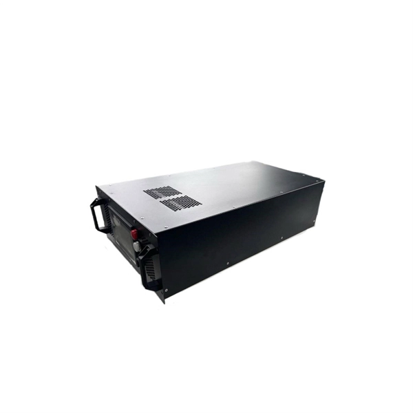
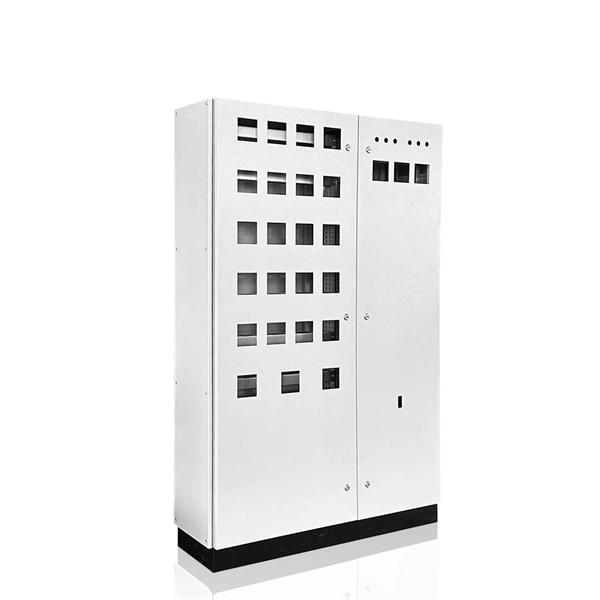
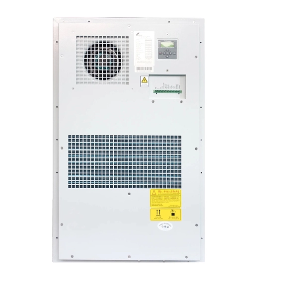
Distribution Box Protection Method
Its primary purpose is to ensure safe and efficient power distribution while providing protection via fuses or circuit breakers against overloads and short circuits. Distribution boxes are built with durable materials, typically metal or high-grade plastic, designed to endure. EPRI has been exploring protective device configuration approaches tar-geted at minimizing the chances of adverse interactions with the power system and the environment. More specifically, electrical faults caused by vegetation, animals, conductor slap, lightning and equipment failures can each. A distribution box, also known as a power distribution box or electrical distribution box, is used to distribute electrical power safely to multiple circuits. Circuit Breakers or Fuses: These safety devices automatically stop the flow of electricity during faults or overloads. Fuses melt when too much current. Electrical systems power our homes, offices, and industrial facilities, but behind every reliable electrical setup lies a crucial component that often goes unnoticed: the distribution box.
[PDF Version]
-
Wiring method for flat iron distribution box
Take the appropriate rating of MCB and RCCB as per your load requirements. Connect the phase and neutral wires from the input power supply to the input of the Main MCB. Connect the output of the Main MCB to the input of the. Learn how to wire a distribution box step by step! This video shows real on-site footage of electrical installation, demonstrating safe and standardized wiring methods used by professionals. Distribution Box Installation: Put the distribution box on the. Material preparation: Prepare the required circuit breakers, wires, wiring ties and other materials, and ensure that they meet the design drawings and installation requirements. Straight lengths are shipped without exterior crating.
-
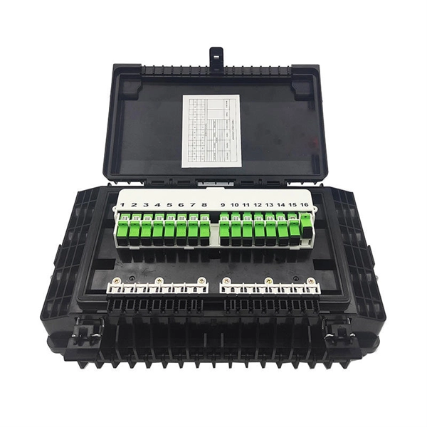
Wiring Method for Optical-to-Grid Module
Optical fibers require special care during installation to ensure reliable operation. Installation guidelines regarding minimum bend radius, tensile loads, twisting, squeezing, or pinching of cable must be followed.
-
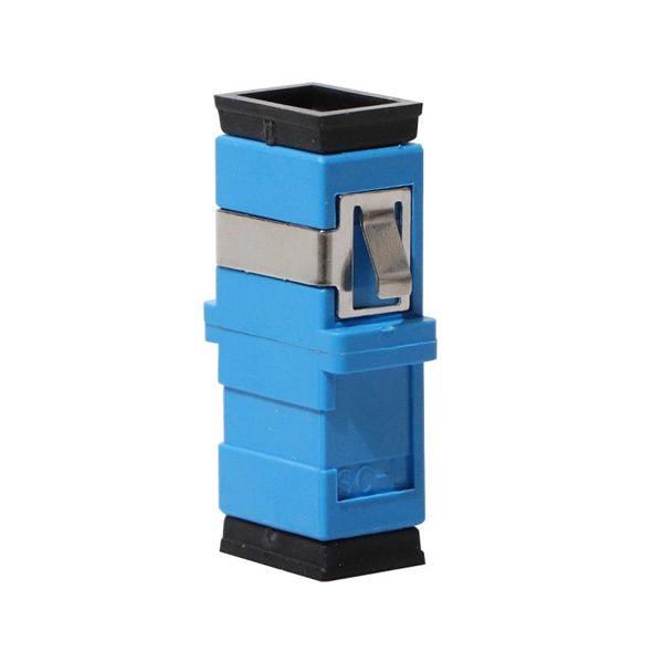
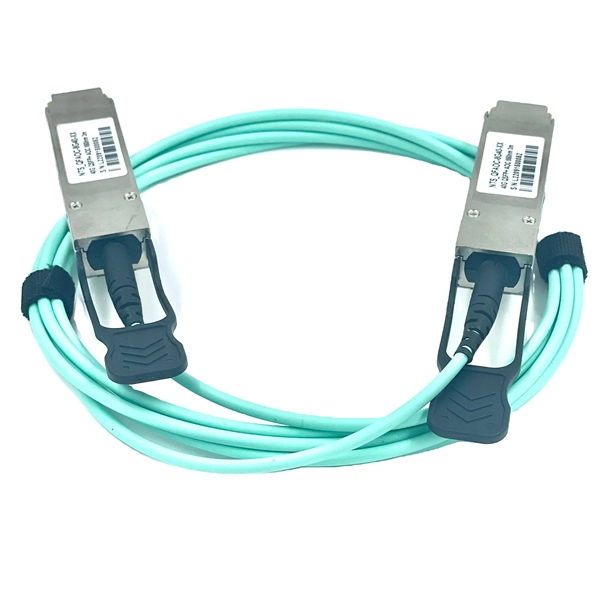
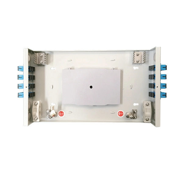
Correct wiring method for jumpers fiber optic cable
Three Polarity Connections Different polarity methods use different kinds of MPO trunk cables. However, all methods utilize duplex patch cords to form fiber optic links. The TIA standard also defines two different types of LC or SC duplex fiber optic patch cords to complete. optic cable is sensitive to excessive pulling, bending, and crushing f rces. Consult the cable specification sheet for the cable you are installing Do not bend the cable more sharply than the minimum recomme ded bend radius. Patch cords are more prone to damage than fiber optic cables, especially. Good management of fiber jumper can not only reduce the operating cost of the entire fiber optic network, make it beautiful and convenient, but also increase the reliability and flexibility of network operation and maintenance. Fiber Cabling and Management In the process of installing and arranging. The Fiber Optic Association, Inc. There are various kinds of fiber jumper cables, including single mode and. How to connect the fiber optic jumper?Optical fiber jumper is a connection line used to connect optical fiber equipment,which plays a vital role in optical fiber communication.
[PDF Version]
-
Wiring Method for Conveyor Belt Distribution Box
This guide explains how to set up the conveyor belt. Start by connecting the 230V AC supply (from a wall socket) to a main switch. Phase 1 (L). Introduction to the wiring method for conveyor belt incoming line – Your Industrial Belts Factory ! The incoming wiring of the conveyor belt is one of the important links in the conveyor belt system. Correct positioning and connection of cables are necessary steps to ensure the normal operation and. intenance, operation and installation of the MDRBC belt conveyor. Let's break it down! Key Components: 1. 3-Phase Voltage Protector (Automatic): This device ensures. Belt Conveyor - Installation, Operation and Maintenance Manual INSTALLATION OPERATION AND AINTENANCE ANUAL INSTALLATION OPERATION MAINTENANCE INSTRUCTIONS BELT CONVEYOR THOMAS MH Safety Manual-v2 PC. indd 61 10/21/2024 3:12:22 PM THOMASCONVEYOR. more Audio tracks for some languages were automatically generated. Learn more How to do Electrical Wiring In this Video, we will learn how we can make a.
[PDF Version]
-
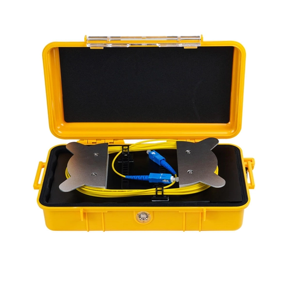
Fiber optic cable lines according to laying method
The routes for laying fiber optic cables may involve ducts, subterranean channels or elevated paths. Installation typically employs two techniques: pulling and blowing. The Fiber Optic Association, Inc. (FOA) was founded in 1995 to help develop the workforce to build the fiber optic networks to support a rapid expansion in communications and the Internet. The charter of the FOA was to promote professionalism in fiber optics through education, certification, and. Below is given the fiber optic cable installation method statement for performing the installation of optical fiber cabling system for any kind and size of project. It forms a critical backbone for modern communication networks across both urban and rural environments.
-

Relay Protection Test Wiring Method
One approach to test the total protection system is to use primary injection techniques (see appendix H) that trigger protective relays and lockout relay, trip circuit breakers, and initiate annunciations and indications. If applicable, documentation is required detailing how verified protection segments overlap to ensure there is not a gap. The purpose of this Standard Work Practice (SWP) is to standardise and describe the method for testing of Ergon Energy protection relays for commissioning purposes. This SWP should be interpreted in conjunction with Standard for Substation Protection (V1. From a technician's perspective, master the unique skill of testing protection. When the transformer wiring type is Y/Y (Y0), the test wiring is very simple: when testing phase A, the tester IA is connected to the phase A of the high voltage side, and the tester IB is connected to the phase a of the low voltage side. After the neutral line of the high and low voltage sides is. Function: Use electronic components like transistors to perform switching. Applications: Frequency, undervoltage, and overcurrent protection.
[PDF Version]
-
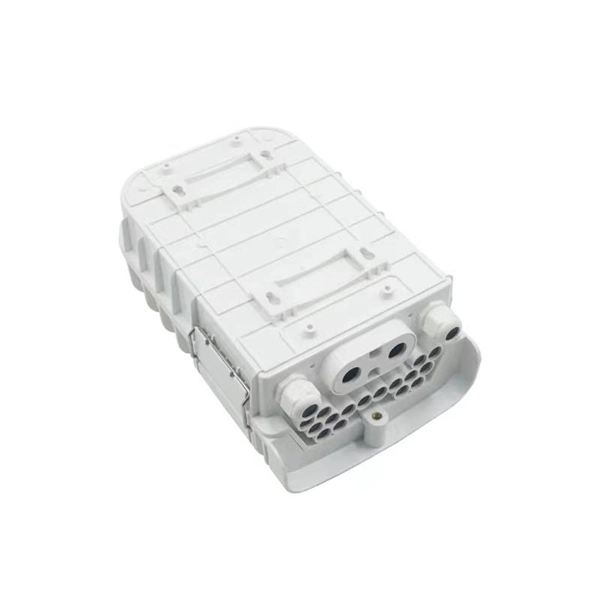
Installation Method for Outdoor Optical Cable Communication
Comply with National Electrical Code requirements for cable ratings and fire safety. Prepare cable ends by sealing gel-filled cables and protecting buffer tubes to prevent water ingress and physical damage. You must follow strict installation guidelines for outdoor fiber optic. Outdoor fiber optic cable is a type of communication cable specifically designed for harsh outdoor environments. Fiber optic technology uses light signals to transmit data. Whether you're a technician, a network planner, or simply curious about fiber optic technology, this article will. The Fiber Optic Association, Inc. Armored cables are ideal for areas with high mechanical stress, while gel-filled. Conducting Site Surveys and Environmental Assessments Before Construction Conduct a thorough site survey before construction begins. Proper preparation helps prevent.
[PDF Version]
-
Installation method of cable tray in distribution box
Spring knot is used to connect cable tray or trunking to channel. Approved and correct fittings are used. Installed containments are free of damages. Whether you're building a commercial setup or upgrading an industrial plant, proper cable tray installation ensures neat wiring, safe access, and easy maintenance. But before you lay the first tray or clamp down a single cable, you need a solid plan. This guide breaks down the process step by step. This guide covers the critical steps, from selecting the right electrical cable tray and performing accurate cable fill. maintain spacing or to keep cables in place when the tray is ect the minimum bend ra-dius for cables as they exit the bottom of the cable tray. A rung spacing of 6 to 9 inches (150 to 230 mm) is preferable when the cable tray cont d for instrumentation and control applications that require. Below is the detailed cable tray installation method statement not only for cable tray but also applicable for GI ladder and trunking for indoor and outdoor applications and in service rooms like pump rooms, electrical rooms and plant rooms etc.
[PDF Version]