-
Wiring of residual current circuit breaker in distribution box socket
In this video, I'll show you the complete wiring diagram of a home distribution board (DB). You'll learn how to connect the main circuit breaker (MCB), residual current device (RCD), and individual circuit breakers for lighting, sockets, and appliances. This guide provides a detailed, professional procedure for installing a Residual Current Circuit Breaker (RCCB)—a device essential for protecting people from the severe danger of electric shock. #dbbox #distribution #home #house. A distribution board or distribution box is where the main power supply is distributed to multiple loads. You will learn to build a safe, efficient, and professional electrical system today.
-
Home electrical distribution box wiring length allowance
The NEC outlines clear rules for how much wire should be left in an electrical box. For any outlet, junction box, or switch point where a connection or splice will be made, there must be at least six inches of free conductor. The Box Fill Calculator is an essential electrical installation tool that determines the maximum number of conductors, devices, and fittings that can be safely installed in electrical boxes according to National Electrical Code (NEC) standards. 16, including conductors, devices, clamps, and grounding. Ensure your installations are safe and code-compliant. Calculate electrical box fill requirements per NEC 314. A conduit body is a removable-cover section of a conduit system that provides access at junctions or termination points.
-
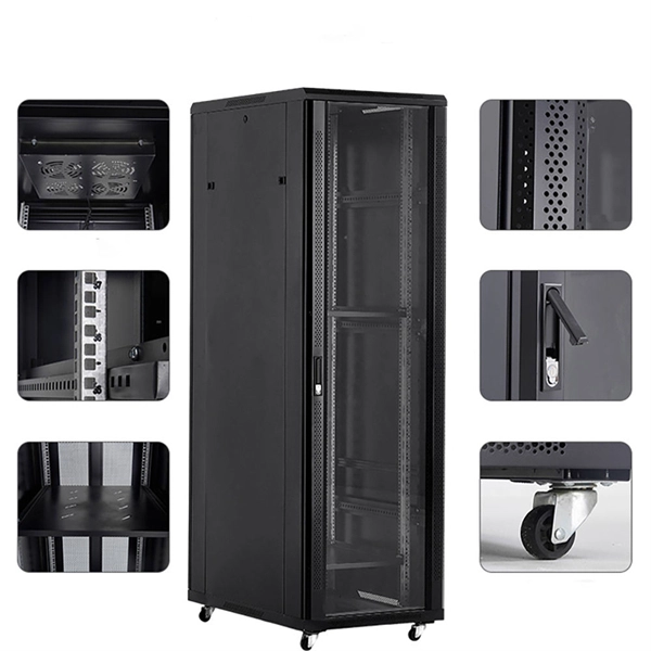
Wiring in distribution box floor cabinet
Wiring arrangement: Arrange the wires neatly in the box, fix them with zip ties, avoid wires from tangling or coming into contact with sharp edges, and reserve a certain amount of space for heat dissipation. A distribution box is the heart of any electrical system. It takes the incoming power and safely distributes it to different circuits throughout your building. more Learn how to wire a distribution box step by step! This video shows real on-site footage of. A well-chosen and properly installed distribution box can prevent electrical hazards, reduce downtime, and ensure your electrical system operates smoothly for years to come. This unique system increases the value of the infrastructure and meets the challenges posed by new construction and renovation in commercial offices, retail outlets an educational facilities. It is usually equipped with circuit breakers, fuses, terminal connectors, and other components. 50” from center of cutout to the.
[PDF Version]
-
Calculation of wiring at the distribution box
Sizing the internal wiring correctly is accomplished by determining the maximum amperage (ampacity) the box will handle, which involves calculating the total connected load. For example, a 50-amp inlet requires a minimum of 6 AWG copper conductor for the main feeder wires (hot . A temporary power distribution box (TPDB), often called a spider box, functions as a portable electrical hub that centralizes and protects power distribution on a job site. Calculate proper wire gauge, voltage drop, and ampacity for safe electrical installations. Our goal? Make sure you never notice it. Before we dive into calculations, let's get familiar with a few essentials: 1. It takes the incoming power and safely distributes it to different circuits throughout your building.
-

Relay Protection Test Wiring Method
One approach to test the total protection system is to use primary injection techniques (see appendix H) that trigger protective relays and lockout relay, trip circuit breakers, and initiate annunciations and indications. If applicable, documentation is required detailing how verified protection segments overlap to ensure there is not a gap. The purpose of this Standard Work Practice (SWP) is to standardise and describe the method for testing of Ergon Energy protection relays for commissioning purposes. This SWP should be interpreted in conjunction with Standard for Substation Protection (V1. From a technician's perspective, master the unique skill of testing protection. When the transformer wiring type is Y/Y (Y0), the test wiring is very simple: when testing phase A, the tester IA is connected to the phase A of the high voltage side, and the tester IB is connected to the phase a of the low voltage side. After the neutral line of the high and low voltage sides is. Function: Use electronic components like transistors to perform switching. Applications: Frequency, undervoltage, and overcurrent protection.
[PDF Version]