-
MEMS optical switch design
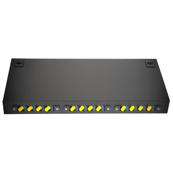
In figure 1.2 a row of protection switches is shown that is used in parallel optical connections (e.g. bus connections between computers). All channels have to be switched at the same time to reroute the signals from one computer to ano. In figure 1.2 a row of protection switches is shown that is used in parallel optical connections (e.g. bus connections between computers). All channels have to be switched at the same time to reroute the signals from one computer to another. Protection switching is required to avoid a permanent interrupt of a connection due to fiber break or due to. mirror / shutter surface micromachining Si-On-InsulatorElectromagnetic actuators are used in optical switches, as these actuators are known from precision machined solutions and the actuating part is a simple coil of many turns of wire. The ferromagnetic materials required in microsystems can easily be realized by sput-tering or electroplating of Permalloy. Additionally, the combination of permanent ma.
[PDF Version]
-
What kind of transmission equipment is optical fiber cable
They consist of a transmitter on one end of a fiber and a receiver on the other end. Most systems use a "transceiver" which includes both transmission and. Unlike copper wires, which are limited by lower data transmission speeds, shorter transmission distances, and higher susceptibility to electromagnetic interference, fiber optic cables offer unparalleled performance and can cover much greater distances without bumping up against signal degradation. These networks rely on advanced optical equipment to transmit data at incredible speeds over long distances. From fiber optic cables to optical power meters, a range of specialized equipment is essential for the successful deployment and maintenance of fiber optic networks. In this article, we will. This technology relies on the transmission of light through thin strands of glass or plastic, allowing for efficient data transmission over long distances. In an era where speed and bandwidth are critical, understanding the principles behind fiber optic cables becomes essential.
[PDF Version]
-
How to strip the outer layer of a double-layer optical fiber cable
FOS03 Fiber strippers remove the coating from the fiber optic cable to expose the glass fiber. Let's explain a little about common layers, and what's important to consider when stripping. This tool is hand held, and has multiple high precision cavities for removing the multiple layers of coatings. These fiber buffer stripping tools provide a quick, easy, and reliable way to remove the buffer from an optical fiber in preparation for connectorization. A fiber guide and matched blades ensure that the optical fiber is correctly positioned and stripped each time.
-
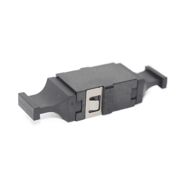
Optical modules are used in switches
Switch optical modules, which convert electrical signals to optical signals and vice – versa, and optical interfaces, which serve as the physical connection points, play a pivotal role in determining the speed, distance, and reliability of data transmission. Everything you need to build an optical network from end-to-end. Common optical module types such as SFP. SFP (Small Form-factor Pluggable) is a compact, hot-pluggable network interface module used to connect network devices (switches, routers, firewalls) to fiber optic or copper cables. Think of it as the “translator” for your network equipment, converting electrical signals into optical signals. Describes what an optical module is and FAQs, including the fundamentals, appearance and structure, key performance counters, common types, and naming conventions of optical modules, causes of optical module failures and corresponding protection measures, types of optical modules supported by. An optical transceiver module, often simply called an optical module, acts as a signal conversion interface in fiber optic networks.
[PDF Version]
-
Want to learn how to fuse 24-core optical fiber cables
Learn how to splice fiber optic cable using fusion splicing with this complete step-by-step guide. Includes tools, best practices, loss standards (ITU-T G. 652), cost analysis, and FAQs for network engineers and installers. In this guide, you will find a chronological description of the fusion splicing process, the principal technical standards, and answers to the real-life questions network engineers and procurement teams may have. Therefore, we will also touch on cost factors, risk management, and best practices in. With this in mind, we have prepared the ultimate guide on how to use a fusion splicer on fiber optic cables. This article provides a detailed explanation of the sequence, covering four aspects: preparation, stripping and cleaning, fusion splicing, and testing.
-
All-optical networking using optical switches
An all-optical Ethernet switch is a network switch whose service ports are entirely optical, meaning every interface uses fiber rather than copper. This design enables end-to-end optical signal transmission, avoiding the conversion between electrical and optical signals at the. Against this backdrop, all-optical Ethernet switches have emerged as a key solution that enables pure fiber-based networking with higher performance and future-ready scalability. Expressed in terms of analog bandwidth, a 1nm waveband translates to a bandwidth of 178GHz at 1300nm and. This paper first summarizes the topologies and traffic characteristics in data centers and analyzes the reasons and importance of moving to optical switching. They can function as core, aggregation, and access devices on campus networks and connect to upstream and downstream devices. ring numer-ous "optical to electrical to optical" (OEO) conversions. Transport is done with static point-to- oint optical links, while swi e connection-oriented data streams from input to output connections. Recent developments in all-optical circuit switching in combination.
[PDF Version]
-
Can bare optical fiber be split into single-mode and multi-mode
Q: Can I mix single mode and multimode fiber type? A: This answer for this question is “no”. Dual fiber modules use two fibers. They are easier to set up and give steady communication. These differences determine which transceivers work with which fiber and how far signals can travel. Understanding the compatibility constraints prevents costly downtime and troubleshooting. This single light path is launched by a narrow‑linewidth laser source, which travels with minimal modal dispersion, allowing the optical signal to preserve its shape over. The mechanism responsible for keeping light confined within the fiber's core is known as Total Internal Reflection (TIR). The primary distinction between single mode and multi-mode fiber optic cable is the fiber core diameter, wavelength & light source. There are two main types of fiber optic cables: single mode and multimode.
[PDF Version]