-
How to connect a two-core optical fiber communication cable
Learn how to splice fiber optic cable using fusion splicing with this complete step-by-step guide. Includes tools, best practices, loss standards (ITU-T G. 652), cost analysis, and FAQs for network engineers and installers. Proper connection of fiber optic cables is essential to harness these benefits fully, as even minor errors can lead to significant performance issues like signal loss. This creates a permanent and low-loss connection. Regardless of the type of fiber network you're deploying, be it for telecom, enterprise data centers, or smart city infrastructure, fusion splicing provides the benefits of. Fiber optic adapters, also known as couplers, play a crucial role in fiber optic networks by providing a connection point between two fiber optic connectors. Fiber optic connectors play an essential role in the realm of optical communication, enabling seamless connections between fiber optic cables.
[PDF Version]
-

How to connect a switch to a fiber optic network
Most modern fiber-enabled network switches require an SFP transceiver module featuring a duplex (two strand) multimode OM3 or duplex single mode OS2 connection with LC connectors. Direct attach cables with pre-terminated SFP connections may also be used. SFP transceiver modules are specific to the type of fiber being connected. Fiber optic cabling is increasingly used to connect network switches and other datacom equipment, especially in long-distance and mission-critical applications. Fiber provides: Increased internet signal bandwidth.
-
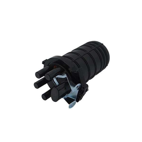
How to connect the spiral armor fiber optic cable
This guide provides a complete installation process for armored fiber optic cords, explaining each step from routing and pulling to stripping, cleaning, and testing. Precision is everything! #satisfy. Armored fiber cable is a fiber optic cable reinforced with additional protective layers to enhance its durability and resistance to external damage. The armor typically consists of. Step-by-step guide to opening spiral steel armor on fiber cables in seconds. Precision is everything! #satisfying #Tools #FiberLife#Engineering#diy#electrician#networking#fiberopticcable#fiberoptic#Networking#CableWholesale#NetworkEngineer#40g#techgear#network#retail Opening spiral steel armored. Leviton offers armored fiber optic cable in a wide variety of optical fiber constructions. QUICK LINKS: ARMOR-TEK™ Fiber Cable and Trunks | Plenum/Riser.
-

How to connect the 10 Gigabit Ethernet cable to the fiber-to-electrical port module
A special 10G Copper RJ-45 Transceiver (10G-SFP-T) is required to connect the SFP+ port to RJ45. It allows connecting a server/storage side Cat6/7 cable to an SFP+ port transceiver. An SFP module (or optical transceiver) converts electrical signals from network devices (switches, routers) into optical signals for fiber transmission and vice versa. 1G/10G SFP+: Standard for Gigabit and 10 Gigabit Ethernet. These transceiver modules are hot-swappable input/output (I/O) devices that plug into 100BASE, 1000BASE and 10GBASE ports (for SFP+), which connect the module port with the fiber-optic or copper network. 4ft (30m) * using Cat6a/Cat7 or above cable for 10G connection in various applications. In this video, we'll guide you through building a high-speed 10G LAN by connecting two fiber switches. Finally, check the transmit (TX) and receive (RX) paths to ensure that signals are aligned.
[PDF Version]
-
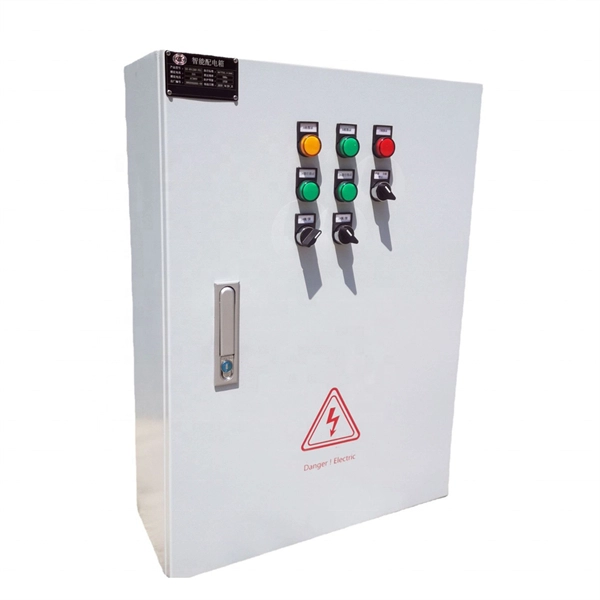
How to connect the light wires to the secondary distribution box
To maintain the parallel connection, the incoming power wires must be spliced with the wires that connect to the first fixture and the new set of wires that will run to the second fixture box. This splicing is accomplished by using a technique called pigtailing. In this video, we'll walk you through the process of wiring a home distribution box with a detailed connection diagram. Single Phase Distribution Box generally consists of Double Pole MCBs, Single Pole MCBs, and RCCBs. How to wire an electrical junction box. A junction box is used to add a spur or to extend circuits and direct power to lights and additional sockets.
-
How to connect cable trays to the ground
If cable trays are to be used as grounding points, their connection points must be grounded using flexible jumpers with lugs of appropriate cross-sections. An EGC conductor in or on the cable tray. There are three wiring. Cable tray systems have become an essential component in the infrastructure of modern commercial buildings, smart offices, data centers, and various industrial facilities. These systems provide an efficient and adaptable solution for managing a wide range of cables, including power cables, control. When setting up electrical systems, grounding is a must. The Cable Tray Grounding Wire ensures everything runs safely and smoothly. In accordance with National Electrical Code (NEC) Article 392 “Cable trays” first determine the Maximum Fuse Ampere Rating or Circuit Breaker Ampere Trip Setting or Circuit Breaker Protective Relay Ampere Trip Setting for Ground-Fault Protection s the minimum.
[PDF Version]
-
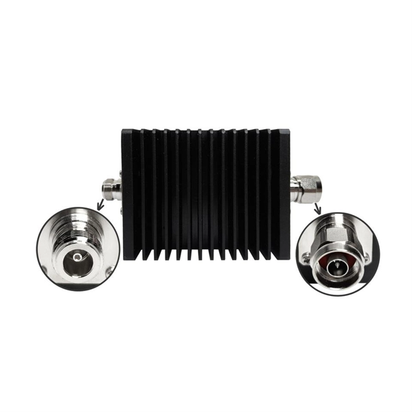
How to connect optical cables to split them into multiple paths
Optical couplers can split or join signals in fibers. These devices work both ways, which helps strong network communication. For example, optical splitters send light to many output ports. You can also use them to join light from. Before attempting to split a fiber optic cable, gather the necessary tools and equipment: Fiber Optic Splitter: This device divides a single optical signal into multiple signals. It typically consists of an MPO connector on one end, which can accommodate multiple fibers, and multiple connectors (such as LC or SC) on the other end, each. Optical splitters offer a cost-effective and dependable solution across various fiber optic applications. Also known as optical splitters, fiber splitters, or beam splitters, these devices are integrated waveguides ensuring wide bandwidth and minimal loss in high-frequency applications. This device takes the incoming light signal and divides it into multiple paths, allowing the signal to be sent to multiple devices.
[PDF Version]
-
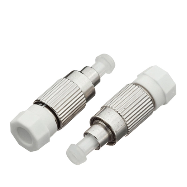
How to connect an lc interface
Here are the detailed epoxy LC connector assembly and termination instructions for both single mode and multimode LC connectors. The steps are pretty generic and are applicable to most major brands' LC connectors on the market, such as those from 3M, Seiko, Corning, Molex, AMP . LC connectors are quickly becoming the connector of choice due to their compact size and outstanding performance. These connectors feature a push-pull coupling mechanism and a 1. 25mm ferrule, making them ideal for high-density applications. The abbreviation LC for fiber optic connectors stands for Lucent Connector and literally means “translucent/transparent. Most fibers can be mechanically stripped without the aid of chemicals or heat. The connectors with PC finishes are completely intermateable with flat. This guide provides a fully updated and industry-ready overview of LC fiber optics, explaining the origin and design of LC connectors, their key features, and the complete ecosystem of LC-based products used in modern networking.
[PDF Version]
-
How to connect a contactor to a distribution box
First, find all the terminals on the contactor. Connect the line and load wires to the right terminals. Make sure. A contactor is an electromechanical switch that allows or interrupts the flow of electric current. It is widely used in applications such as motor control, lighting control, and power distribution. A contactor wiring diagram is a graphical representation of how contactors and other electrical. Properly wiring a contactor means connecting the control circuit to the coil terminals (A1/A2) and the high-voltage power circuit to the line (L1/L2/L3) and load (T1/T2/T3) terminals.