-
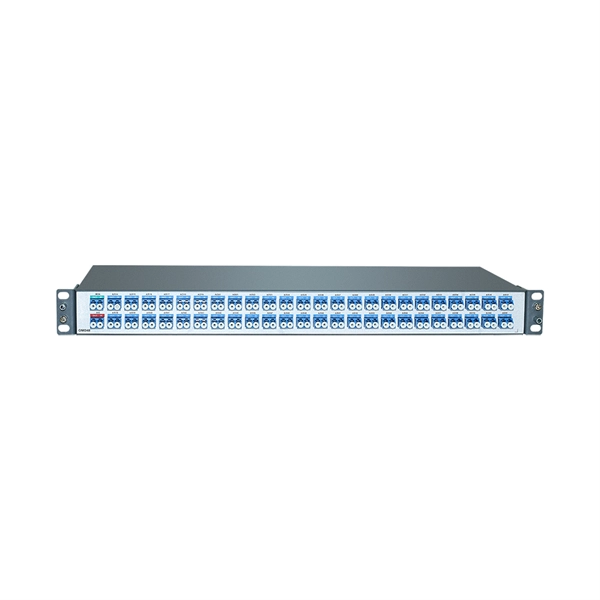
Secondary distribution box main switch
Secondary selective service achieves similar results by using switches on secondary voltages rather than primary voltages. With secondary selective service, each distribution transformer must be a.
-
The main distribution box should use a four-pole switch
At incoming feeders or main distribution panels, always select 4P isolators or MCCBs (Molded Case Circuit Breakers). Standard IT systems usually do not provide a neutral line to the user, meaning a 4th pole is unnecessary. The correct choice depends on earthing system type and protection. In low-voltage three-phase four-wire distribution systems, disconnect switches, circuit breakers, or load switches are typically installed at the power source end of the distribution circuit. Their main functions are to disconnect or connect the circuit during normal operation, maintenance, or in. The choice between a 3-pole and 4-pole circuit breaker is often determined by the type of electrical system in use and the specific protection requirements. A 1P breaker handles one live wire. And if your system has significant neutral. When planning for systems, it is important to consider whether the UPS will be centralized or permanently connected and to use 3- and 4-pole devices appropriately for their locations and to ensure proper functionality of electrical systems. TP MCB: It is most commonly used type in all ordinary three phase supply.
[PDF Version]
-
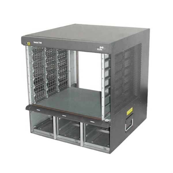
Inspect the power distribution box switch box for faults
Check the electrical load and ensure that the sensors do not exceed the 10 Amp maximum. Power distribution & circuit protection depend on it. LV intrusive switchboards accept power from the utility & generator & distribute it to building circuits. Ensure that all labels and warning signs are legible. Internal Inspection Open the distribution box and check for. Diagnose the fault in a low voltage distribution box by checking for overheating, loose connections, and using voltage testers for safe troubleshooting.
-
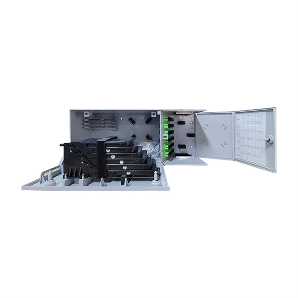
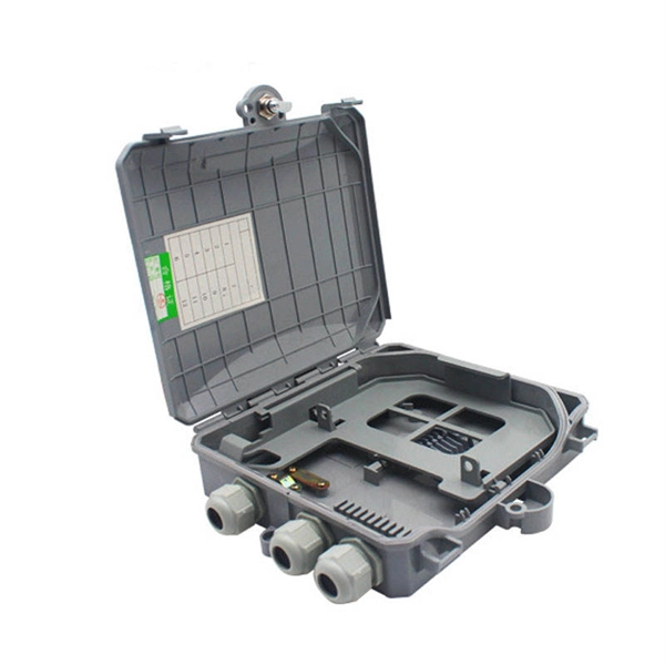
Fiber Optic Terminal Box Serial Connection Method
In network cabling, outdoor connections generally use fiber optic cables. When these optical fibers are installed or laid out, a Fiber Termination Box, or FTB, is used to distribute and protect the optical fiber link.
-
Distribution Box Protection Method
Its primary purpose is to ensure safe and efficient power distribution while providing protection via fuses or circuit breakers against overloads and short circuits. Distribution boxes are built with durable materials, typically metal or high-grade plastic, designed to endure. EPRI has been exploring protective device configuration approaches tar-geted at minimizing the chances of adverse interactions with the power system and the environment. More specifically, electrical faults caused by vegetation, animals, conductor slap, lightning and equipment failures can each. A distribution box, also known as a power distribution box or electrical distribution box, is used to distribute electrical power safely to multiple circuits. Circuit Breakers or Fuses: These safety devices automatically stop the flow of electricity during faults or overloads. Fuses melt when too much current. Electrical systems power our homes, offices, and industrial facilities, but behind every reliable electrical setup lies a crucial component that often goes unnoticed: the distribution box.
[PDF Version]
-
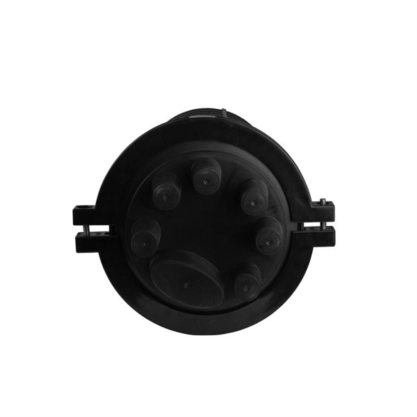
Grounding method for motor distribution box
The most common method of providing for grounding in NEMA motors is a ground lug under one of the conduit box mounting bolts. This is standard in CORRO-DUTY® motors. Each DISTRIBUTION BOX and controller must be grounded. 26 mm 2 (10 AWG) ground wire must be used, and in all other markets a 6 mm 2 must be used. Grounding of the units: Attach a ground wire from one of. Grounding is a mechanism to protect distribution equipment and people under normal operating conditions, abnormal operational (overcurrent and overvoltage) responses, and hazardous conditions such as shocks. Next, we describe directional elements suitable to provide ground fault protection in solidly- and low-impedance grounded distribution systems. The specific neutral grounding method chosen by the utility can have significant impacts on reliability of service, safety, protection coordination, power.
[PDF Version]