-
Calculation of steel structure for cable trays
The calculator supports multiple tray sizes (100-600mm), various cable types, and provides detailed formulas for fill ratio, weight estimation, and structural analysis. Tip: Standard mesh configurations are 25×50mm or 50×50mm. Smaller mesh provides better support for. Cable racks (also called cable trays or cable support systems) are essential structural elements used in industrial plants, substations, commercial buildings, and infrastructure projects. These racks safely support and organize electrical cables, ensuring durability, accessibility, and safety. It is used to manage cables for light B manufactures its cable tray in a range of materials with a variety of finishes. A properly designed and installed cable tray system will provide. Calculate NEC-compliant wire basket cable tray fill, load capacity, and hardware requirements for professional installations. rnese calculations contain an unverified assumptionts) that must be verified later.
[PDF Version]
-
Requirements for Relay Protection Design
The IEEE standard for protection relays refers to a collection of guidelines developed by the Institute of Electrical and Electronics Engineers. This document provides recommendations, background and philosophy on relay protection that is not available in M07. They are intended to quickly identify a fault and isolate it so the balance of the system continue to run under normal conditions. For professionals working in utilities, industries, or renewable energy systems, understanding these standards is not optional—it is essential. This handbook covers the code of practice in protection circuitry including standard lead and device numbers, mode of connections at terminal strips, colour codes in multicore cables, dos and donts in execution.
-
WDM Fiber Optic Communication System Design
This lesson demonstrates the basic features of a typical WDM optical communication system and shows the basic design steps with OptiSystem. The performance of the system will be shown and compared. In fiber-optic communications, wavelength-division multiplexing (WDM) is a technology which multiplexes a number of optical carrier signals onto a single optical fiber by using different wavelengths (i. Single mode fiber is favored over Multimode fiber for long-distance communication. Firstly, the WDM optical. While fiberoptic technology resulted in a significant increase in a network's "bandwidth," or the amount of information that the network could send, tbe creation of the Internet resulted in an even greater demand for bandwidth. As demand for network capacity increased, service providers exhausted.
-
Optical Module Base Design
Optical module usually consists of a transmitter assembly (TOSA, containing a laser LD chip), a receiver assembly (ROSA, containing a photodetector PD chip), a driver circuit, an optoelectronic interface, a heat sink (some models), a housing, a pull ring and so on. Integrated circuits and reference designs help you create a smaller and faster optical module design used in high-bandwidth data communication applications. Whether you are creating a 100-Gbps or 400-Gbps, small form-factor pluggable (SFP) module, SFP+ transceiver, XFP module, CFP, X2/XENPAK module. Designing and producing these complex PCBs presents formidable challenges, requiring a convergence of disciplines—from high-frequency signal integrity and advanced thermal management to micron-level mechanical precision. These three laser diodes are described in more detail. contact us product page Copyright © 2024 MVSLINK. Critical Metrics: Signal integrity (insertion loss, return loss) and thermal management are the two.
[PDF Version]
-
Optical Module Lens Design
Looking to learn about optics and optical design? Learn the basics of optics needed to begin designing optical systems in this educational, online Fundamentals of Optics course co-created by E.
-
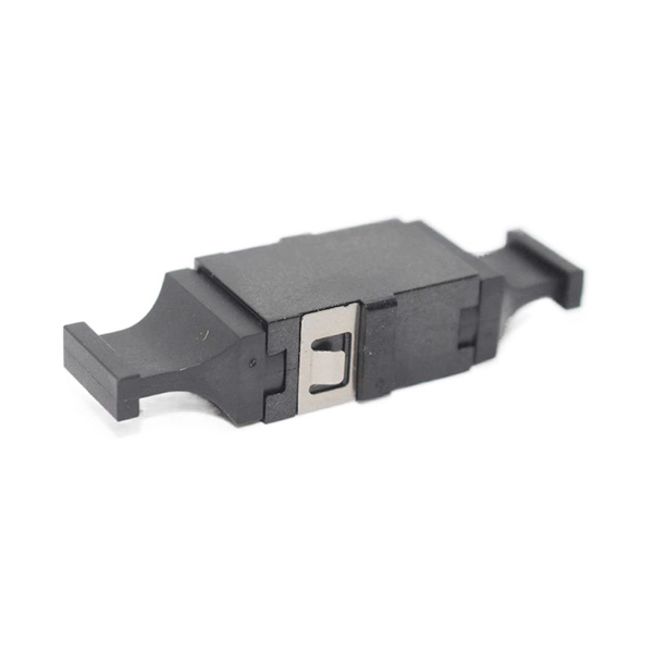
MEMS optical switch design
In figure 1.2 a row of protection switches is shown that is used in parallel optical connections (e.g. bus connections between computers). All channels have to be switched at the same time to reroute the signals from one computer to ano. In figure 1.2 a row of protection switches is shown that is used in parallel optical connections (e.g. bus connections between computers). All channels have to be switched at the same time to reroute the signals from one computer to another. Protection switching is required to avoid a permanent interrupt of a connection due to fiber break or due to. mirror / shutter surface micromachining Si-On-InsulatorElectromagnetic actuators are used in optical switches, as these actuators are known from precision machined solutions and the actuating part is a simple coil of many turns of wire. The ferromagnetic materials required in microsystems can easily be realized by sput-tering or electroplating of Permalloy. Additionally, the combination of permanent ma.
[PDF Version]
-
Does OPGW fiber optic cable require steel strand
AFL HexaCore Optical Ground Wire (OPGW) cable utilizes fiber-bearing stainless steel tubes stranded alongside aluminum clad steel and/or aluminum alloy wires to create a multi-layer cable design suitable for a variety of environmental and geographical conditions. Tubes are stranded with multiple layers of aluminum-clad or steel wires. Product Description OPGW power optical cable is an overhead ground wire containing optical fibers, which has multiple functions such as. er request.
-

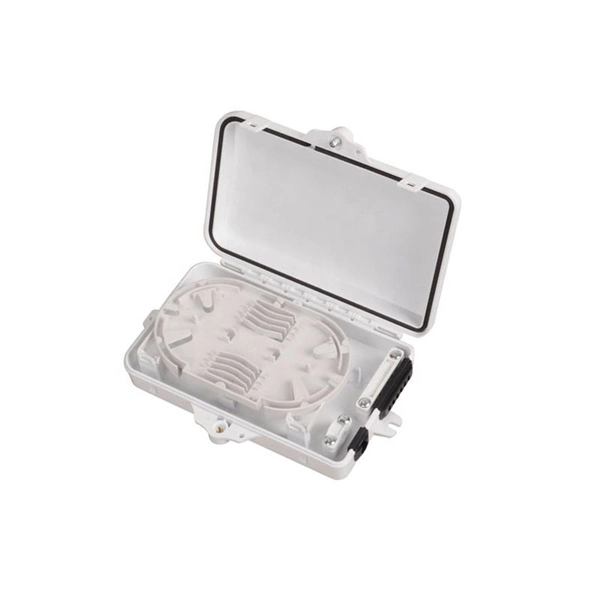
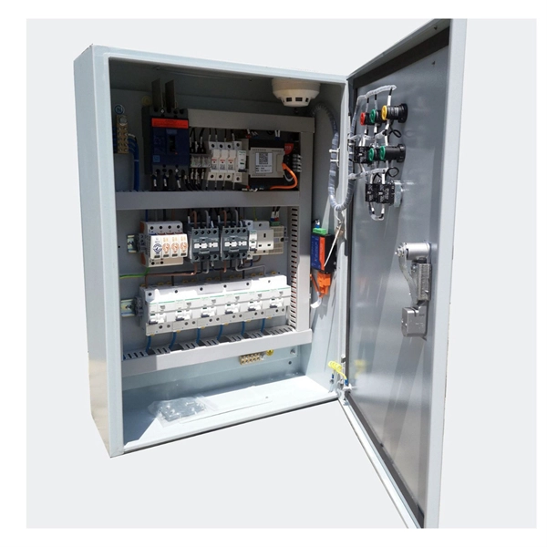
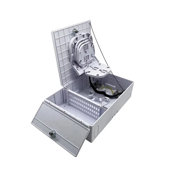
Grenada Stainless Steel Distribution Box Configuration
Here you can download the program for the configuration of our electrical cabinets. This weatherproof project case is designed to conceal, protect and protect your various outlets, plug-ins, power cords and other vulnerable equipment from the weather, ensuring your holiday and landscape lighting, patio heaters, fountain pumps, Maximum safety for power tools and other electrical. The underground transformer is a new type of compact substation equipment that combines a transformer, high-voltage load switch, fuse, and other components. It is installed in a pit, does not occupy surface space, and can operate submerged in water for a period of time. They are particularly suitable for applications under extreme environmental conditions, and they provide reliable protection under heavy loads. The housings are made from. An outdoor distribution box is a protective enclosure used to house electrical connections, circuit breakers, and wiring components in external environments. The enclosure is made of 201, 304 or 316 stainless steel. Its protection degree can reach IP55 or IP66.
[PDF Version]