-
What are the components of high and low voltage complete sets of equipment
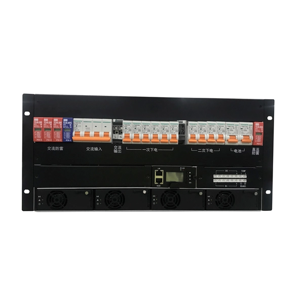
High and low voltage complete sets of electrical equipment refers to the combination of electrical equipment components including circuit breakers, isolating switches, load switches, fuses, voltage transformers, current transformers, lightning arresters and other electrical. High and low voltage complete sets of electrical equipment refers to the combination of electrical equipment components including circuit breakers, isolating switches, load switches, fuses, voltage transformers, current transformers, lightning arresters and other electrical. High voltage and low voltage complete sets occupy a significant place in modern electrical engineering as they are responsible for safe, secure, and efficient power distribution to all types of industries. They are known as complete switchgear assemblies because they integrate inside them such. Electrical switchgear is a complete set of equipment composed of circuit breakers and isolation switches. Like switchgear, circuit breakers, load switches are in this category; control equipment, contactors, relays; protection equipment including fuses, over-voltage protector; and.
[PDF Version]
-
Latest Standards for Relay Protection Withstand Voltage Test
IEC 60255-5 is the standard that defines insulation coordination for these devices — the test voltages, impulse withstand levels, and minimum insulation resistance values that every protection relay must meet. This article breaks down the standard's requirements with the specific clause numbers and. Abstract: Design tests for relays and relay systems that relate to the immunity of this equipment to radiated electromagnetic interference from transceivers are specified in this standard. Two types of tests are specified: the oscillatory (SWC) and. IEEE Standard for Relays, Relay Systems, and Control Devices used for Protection and Control of Electric Power Apparatus--Surge Withstand Capability (SWC) and Electrical Fast Transient (EFT) Requirements and Tests Abstract: Design tests for relays, relay systems, and control devices used for.
[PDF Version]
-

Relay protection voltage and current signals
A protection relay is a crucial component of electrical systems that safeguard infrastructure, employees, and equipment from electric problems and malfunctions. It. Reference Design to Measure AC Voltage and Current in Protection Relay With Delta-Sigma Chip Diagnostics (Rev. A) This high-accuracy analog front-end (AFE) reference design measures analog input performance and includes chip diagnostics to help identify power system failures using AC voltage and. The rectangular devices are test connection blocks, used for testing and isolation of instrument transformer circuits. In electrical engineering, a protective relay is a relay device designed to trip a circuit breaker when a fault is detected. ABB Type SAB Current Transformer CT's transform line current down to a signal level that is acceptable to the relay.
-

Circuit Breaker Relay Protection Equipment Model
Microprocessor-based solid-state digital protection relays now emulate the original devices, as well as providing types of protection and supervision impractical with electromechanical relays.OverviewIn, a protective relay is a device designed to trip a when a is detected. The first protective relays were electromagnetic devices, relying on coils operating on moving par. Electromechanical protective relays operate by either, or. Unlike switching type electromechanical with fixed and usually ill-defined operating voltage thresholds. Electromechanical relays can be classified into several different types as follows: "Armature"-type relays have a pivoted lever supported on a hinge or knife-edge pivot, which carries a moving contact. These relays may.
-
Phenomena of relay protection failure
It occurs when the relay fails to adequately connect or disconnect its contacts in response to a fault or abnormal condition. This project investigated failure modes of control, timing, auxiliary, and protective relay models in service in U. Although the data utilized is from U. This theoretical side has its practical s on Hidden. Selectivity is a mandatory requirement for all protection, but the importance of it depends on the application. For example, unselective protection operation during a medium voltage network fault will cause an outage for an unnecessarily large number of consumers. However, like any electrical device, relays can experience failures that compromise their intended function.
-
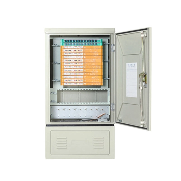
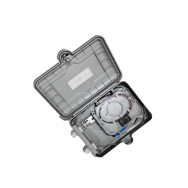
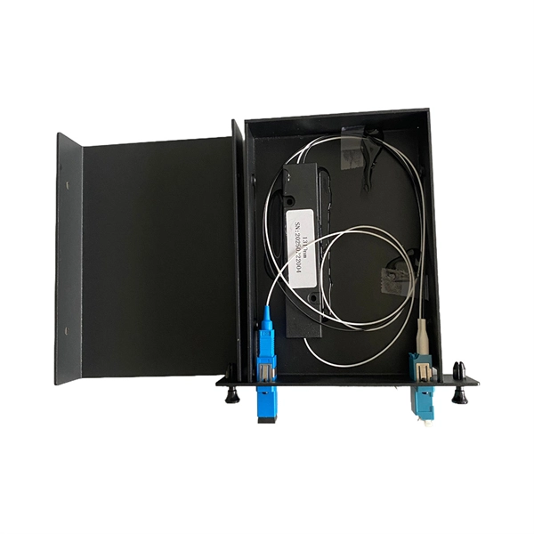
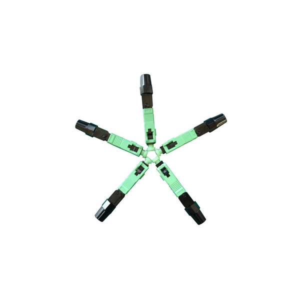
What category of equipment does optical fiber cable belong to
Fiber optic cables are a type of networking cable that uses light to transmit data. Unlike traditional copper cables that use electrical signals, fiber optics rely on pulses of light to carry information, making them faster and more efficient over long distances. It offers significantly improved performance in terms of both bandwidth and data carrying than traditional metal conductor alternatives. What is Optical Fibre? Fiber or fibre optic technology is an effective cabled-based communication system. Why are optical fiber cables important? High Bandwidth: Supports faster data. Fiber optic cable powers modern communication across telecom networks, broadband infrastructure, industrial systems, defense platforms, marine environments, ROV operations, and custom engineered applications. It is about transmission distance.
-

Relay protection circuit protection
Distance relays, also known as impedance relay, differ in principle from other forms of protection in that their performance is not governed by the magnitude of the current or voltage in the protected circuit but rather on the ratio of these two quantities.OverviewIn, a protective relay is a device designed to trip a when a is detected. The first protective relays were electromagnetic devices, relying on coils operating on moving par. Electromechanical protective relays operate by either, or. Unlike switching type electromechanical with fixed and usually ill-defined operating voltage thresholds.
-

Requirements for Instrument Transformers in Relay Protection
This guide provides a comprehensive overview of various transformer protection schemes and offers recommendations for relay selection, coordination, and settings. Another important standard is the IEC 61850, which focuses on communication protocols for substation automation systems. He worked for Consolidated Edison Company for ten years as a System Engineer. In some cases, a user may apply the techniques described in this guide for protecting. provide protection is the fault that initially involves one turn. These harm time during each cycle where the current magnitud unit (PU) on transfo acteristics that relate fault-current magnitude to. Transformers Committee IEEE 3 Park Avenue New York, NY 10016-5997 USA IEEE Power and Energy Society IEEE Std C57. 13™-2016 (Revision of IEEE Std C57. 13-2008) Authorized licensed use limited to: University of Waterloo. Basler also offers turnkey engineering services through their Basler Services, LLC subsidiary. Basler products control and.
[PDF Version]
-
High Current Relay Protection Tester
The CMC 356 is the universal six-phase testing solution for all generations and types of protection relays, where highest versatility, amplitude and power are required.
-
Why do relay protection phenomena occur
Protective relays monitor electrical parameters such as current, voltage, and frequency to detect anomalies in the system. In industrial power systems, Protection relays are expected to operate with high precision, isolating faults while keeping healthy parts of the network energized. However, in many real-world plants, failures are not caused by relay hardware itself but by incorrect configuration, outdated settings. These relays play a crucial role in the protection of transformers, generators, transmission lines, and other critical components by automatically isolating the faulty section when needed. It functions as a watchdog by constantly surveying multiple system components including voltage, current, frequency, and phase angle.
-
Protection level of busbar connectors
The International Electrotechnical Commission (IEC) sets out standardized testing procedures and benchmarks to ensure that busbar contact resistance remains within safe and acceptable limits. IEC standards are developed through international consensus and are used globally. The integrity of busbar joints is critical because. Busbars in power systems are the location where transmission lines, generation sources, and distribution loads converge. Because of this convergence, short circuits located on or near the busbar tend to have very high magnitude currents. The high magnitude fault currents require high-speed. Industry data shows that loose or improperly torqued busbar connections account for a significant percentage of electrical panel failures. Busbar distribution ensures these requirements are fully met. Performance criteria of. DEFINITIONS.
[PDF Version]