-
How to test the continuity of pigtail fiber
A visual fault locator (VFL) makes use of a visible spectrum laser light to test the continuity of the fiber and detect fault conditions. There are two reasons we may want to test bare fiber, by that we mean fiber that has not been terminated in connectors but is simply plain optical fiber, The first one is to ensure the fiber or cable being manufactured meets its specifications, as is done by every manufacturer. Fiber optic. The Optical Time Domain Reflectometer (OTDR) will be used to test splice loss and to conduct span analysis. An Optical Power Meter and Laser Light Source will be used to measure power loss on each completed ring or distribution span to verify continuity between fibers (no fibers incorrectly spliced. A visual check is often the first step when diagnosing a defective fiber pigtail. Continuity testing verifies that the fiber is intact and that light can pass through from one end to the other without any blockages. This comprehensive guide will equip you with the knowledge and skills to accurately assess the integrity of a pigtail, helping you identify issues.
[PDF Version]
-
How does the optical module test group perform its tests
Optical modules will go through strict testing and quality inspection procedures before shipment, such as material testing, parameter testing, aging testing, real machine testing, end-face testing, etc. In fiber optic networks, optical transceivers such as SFP, SFP+, QSFP28, and QSFP-DD play a vital role in converting electrical signals into optical signals and vice versa. Testing these modules ensures performance, compatibility, and long-term reliability in bandwidth-intensive environments like. QSFPTEK suppliers have strict transceiver testing and quality control processes, and each optical module is delivered with a complete testing process. Optical modules can realize end-to-end signal transmission, and it performs optical communication through optical fibers. However, due to the architectural differences between 4-channel and.
[PDF Version]
-
How to test a photovoltaic panel with a multimeter
Testing solar panels is easy with a multimeter! To test the current, simply connect the multimeter to the panel's output. Whether you're a seasoned solar enthusiast or a newcomer to the world of renewable energy, knowing how to use a multimeter to test your solar panels is a valuable skill that can empower you to take control of your energy production. Measure Voc (open circuit voltage) — if it reads 0V, the panel or wiring is dead. If Voc is normal but the system is not producing, the problem is downstream. Solar panels are usually tested under standard conditions using a light source that mimics the light from the sun on a clear day. This helps you spot issues early and keep your system running efficiently.
-

How to test a 1 2 beam splitter
To accurately measure optical splitter loss, utilize optical test equipment like power meters and spectral analyzers. Here's how: Measure the optical power at both the input and output ports of the splitter. What are Optical Splitters? The fiber optic splitter is a device used in fiber optic networks to divide a single optical signal into multiple signals. A beam splitter or beamsplitter is an optical device that splits a beam of light into a transmitted and a reflected beam. In its. This article explains how to create a beam splitter cube in Sequential Mode. Note that jT j2 is the transmitted intensity. I have been looking and either I can't find what I am looking for, or I just get. Page 5 Outline of Product Manual Outline of Product Manual The entire documentation of the hydraulic stone and concrete splitter includes: Product Manual – Information Manual (IM) – for the operator of the device – Operating Manual (OM) – for the operator and –. Table of Contents (IM) Table of.
[PDF Version]
-
How to test a properly spliced optical cable
The most common methods for testing fiber optic splices are optical time-domain reflectometry (OTDR) and optical loss test set (OLTS). For every fiber optic cable plant, you will need to test for continuity, end-to-end loss and then troubleshoot the problems. If it's a long outside plant cable with intermediate splices, you will probably want to verify the individual splices with an OTDR also, since that's the only way to make. That's where splicing comes in—and knowing how to properly splice a fiber optic cable is a critical skill for any technician. Splicing allows you to restore or expand fiber networks while maintaining signal integrity. Fiber optic testing of a newly installed system not only verifies that the system meets its design requirements, but also creates a performance baseline for all future testing and troubleshooting of t at system.
[PDF Version]
-
How to test the continuity of a multimode fiber optic cable
The three standard methods for testing fiber optic cabling are a visible light source, power meter and light source, and optical time domain reflectometer (OTDR). Fiber optic testing for continuity is crucial in ensuring that light transmits through fiber optic cables without interruptions, safeguarding seamless data transmission. As the components like fiber, connectors, splices, LED or laser sources, detectors and receivers are being developed, testing confirms their performance specifications and helps. Fiber optic testing ensures the performance and reliability of fiber optic networks. It helps minimize downtime, reduce maintenance costs, and support system upgrades or reconfigurations. If it's a long outside plant cable with intermediate splices, you will probably want to verify the individual splices with an OTDR also, since that's the only way to make.
[PDF Version]
-
How to connect the fiber optic test patch cord
Just use the one-jumper reference method to set the reference and an adapter to connect the jumper to the test reference cord. You can put in a fibre patch cord at home. You just need to follow easy steps and be careful. Unfortunately, equipment cords are also. Correct patch-cord installation is essential for maintaining low insertion loss, stable return loss, and long-term reliability in both indoor and outdoor fiber networks. This guide addresses expert-certified best practices applied by professionals in the telecommunications, data. Watch as we demonstrate the testing process for 12-fiber MPO patch cords using a laser source. more Watch. In today's high-performance networks, fiber optic patch cables are the lifelines that ensure smooth data flow across switches, servers, and routers. Even the most advanced optical transceivers can only perform at their peak when paired with properly installed, clean, and precisely managed fiber.
[PDF Version]
-
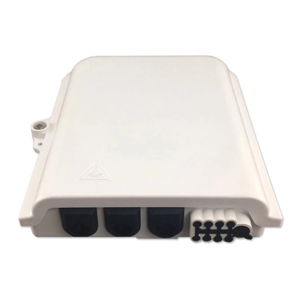
How many cores does the fiber optic distribution box have
Capacity: 8/12/16/24/36/48 cores standard; custom higher counts available. Adapters: LC/SC/FC/ST simplex or duplex panels; APC/UPC compatible as required. To help you choose the right solution for your FTTx deployment, we have categorized our extensive range of Fiber Distribution Boxes (FDB) based on their fiber core capacity and typical application environments. Installer-Friendly Layout: Hinged covers, clear port labeling, bend-radius guides, and strain-relief points accelerate on-site work and reduce. Fiber distribution boxes for FTTH network termination and distribution. Wall mount, floor mount, and rack mount options with capacities from 2 to 144 cores.
-
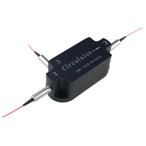
How to fuse single-mode dual-core optical fibers
Learn how to splice fiber optic cable using fusion splicing with this complete step-by-step guide. Includes tools, best practices, loss standards (ITU-T G. 652), cost analysis, and FAQs for network engineers and installers. This article demonstrates the use of several fiber coupling efficiency analyses in OpticStudio. This article demonstrates how to set up a coupling system. Thorlabs offers a varied selection of single mode (SM), polarization-maintaining (PM), multimode (MM), and double-clad fiber couplers, as well as 1x8 and 1x16 SM PLC splitters; 1x4, 1x8, and 1x16 PM PLC splitters; wideband multimode circulators; RGB combiners; and WDMs. Single-mode fibers allow only a single mode of light to propagate through the core, resulting in less signal dispersion and higher bandwidth capabilities. Regardless of the type of fiber network you're deploying, be it for telecom, enterprise data centers, or smart city infrastructure, fusion splicing provides the benefits of. Fused couplers are used to split optical signals between two fibers, or to combine optical signals from two fibers into one fiber. 2-core o In optical modules, "core".
[PDF Version]
-
How to check optical loss on a Huijue switch
Execute the command, display transceiver [ interface interface-type interface-number | slot-id ] [ verbose ] to check the optical module information on the device interface. During use, reading optical module information helps understand its real-time operating status, enabling faster troubleshooting of link abnormalities. The following uses the. Here is an example on how to query or display optical power of an interface in a Huawei Router. from transceivers Check “Alarm information” section for warnings, LOS Alarm means no inbound signal, execute display this to check shutdown mode, execute undo shutdown if necessary. Execute the command, display.