-
Method for calculating the intensity of the optical port of a beam splitter
Where intensity is in W/m² when power is in watts and area is in m². Rectangular spot: A =. T E3 + RE4, where T; R are the transmission and re ection coe cients for the beam splitter. Note that jT j2 is the transmitted intensity. The transformation matrix is then given by The elements of the beam splitter transformation matrix B are determined using the. The theory of the beam splitter (BS) in quantum optics is well developed and based on fairly simple mathematical and physical foundations. This theory has been developed for any type of BS and is based on the constancy of the reflection coefficients R (or the transmission coefficient T, where R + T. The Gaussian beam model provides a solution to the wave equation that describes the distribution of an electromagnetic field in free space or guiding structures like optical fibers. We use elementary laws of classical and quantum optics to obtain general relations among the magnitudes and phases of these probability amplitudes.
[PDF Version]
-

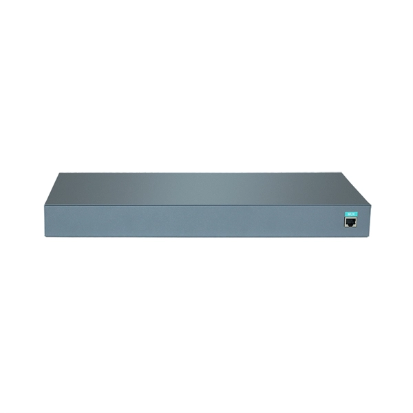
Check the fiber-to-electric port of the switch
Check that the optic cable is in good shape. Use an optical power meter: it can verify the transmit power of an SFP and fiber. Troubleshooting Tip: Verify FortiGate Configuration for SFP TransceiversThis article describes steps to perform when SFP/SFP+ fiber link is not coming up. Scope FortiSwitch and FortiGate. The table describes the LED status indicators for Ethernet modules or fixed-configuration switches: Ensure that both sides have. If you run fiber or copper uplinks in a small office, home lab, or data closet, SFPs (and SFP+) are the little parts that keep your links alive. Log in to the switch using appropriate credentials (username and password). For network engineers, knowing how to view and interpret SFP information from the Cisco command-line interface (CLI) is essential.
-
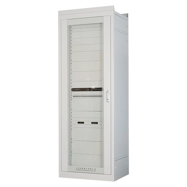
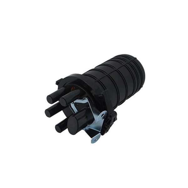
How to open the network cabinet cable inlet port
Use the front and rear rectangular cable-access openings on the top of the rack cabinet to route external cables and to control the flow of air inside the rack. Step-by-step guide: In this way, patch panels, switches, cable routing and documentation are. Do you have a question about the SmartCabinet and is the answer not in the manual? Page 1 SmartCabinet™ User Manual. Page 2 Customer Service Hotline: 4008876510 India Email: customer. If you don't have a good network cable management strategy in place, not only you. more Hello everyone this is Hafiz with you and welcome to my channel. Thus, organizing cables is an integral part of rack mount cable management.
-
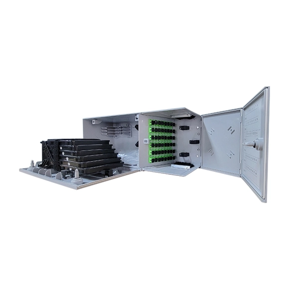
Cascaded port beam splitter splitting ratio
Cascaded (multi-level) splitting: First a splitter closer to CO of smaller ratio (e., 1×4), then further downstream another splitter (e. Pros: fewer feeder fibers from CO, better for wider geography or less dense zones. This guide focuses on two critical aspects of optical splitters that define FTTH performance: split ratios (how signals are divided) and splitting architectures (how splitters are deployed). By understanding these elements, network operators can design PON (Passive Optical Network) systems that. For every 2X increase in split ratio, power is reduced by roughly 3 dB. In most cases, the power out of each leg is equal, but we'll discuss a version where the power coming out is unequal amongst legs. Splitters with. Traditional GPON networks often employ 1:32 or 1:64 splits, while XGS-PON allows higher ratios such as 1:128. However, higher splits reduce the power margin and limit reach, so engineers must carefully calculate the optical budget. In this case, there would be.
[PDF Version]
-
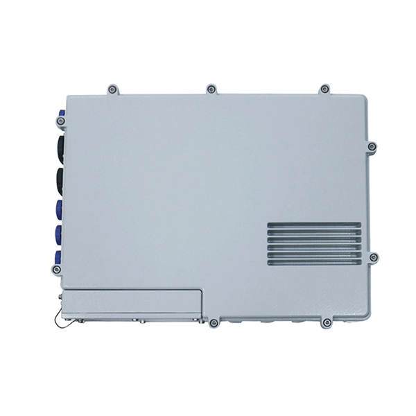
Does the optical port include a module
An optical port is a physical interface used to connect fiber optic cables. Currently, mainstream optical modules include SFP and QSFP form factors, with transmission rates ranging from 2M to 100G. Unlike fixed RJ45 copper ports, SFP ports support both fiber and copper modules, enabling far longer distances, greater flexibility, and improved scalability in enterprise. An electrical port module, also known as an optical-to-electrical port converter module, is a hot-swappable device with an SFP form factor. In addition, because the transmission distance of electrical port. The optical module serves as a crucial component in optical fiber communication systems, operating at the physical layer, which is the lowest layer in the OSI model. Its primary function is to achieve optoelectronic conversion by converting electrical signals into optical signals and vice versa.
[PDF Version]
-
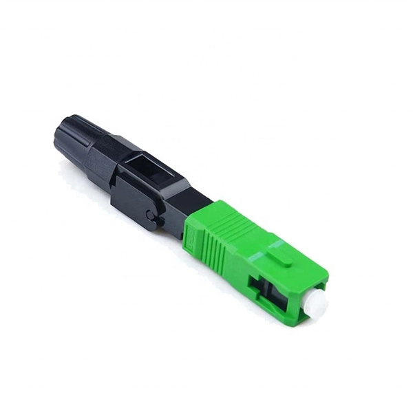
Connect the optical module to the router port
Plug the SFP module into the router's SFP port for fibre optic connectivity. No additional settings need to be made. The assignment of any port on the built-in managed switch of the router can be changed according to the user's. Small Form-factor Pluggable modules (SFP module) are the workhorses of modern network connectivity, enabling flexible fiber optic or copper links between switches, routers, firewalls, and servers. Whether you're upgrading bandwidth, replacing a faulty unit, or reconfiguring your topology, knowing. The SFP+ port is a high-speed optical-to-optical signal conversion port, mainly used for 10G Ethernet and Fiber Channel network applications. They enable high-speed connections between active equipment and allow system scalability without the need for full infrastructure replacement. 1G/10G SFP+: Standard for Gigabit and 10 Gigabit Ethernet. Step 1: Gather the Necessary Equipment To connect your fiber optic cable to a router, ensure you have the following: Fiber optic modem (ONT): Most fiber connections require an Optical Network Terminal (ONT), provided by your ISP.
[PDF Version]
-
Change the core switch port to trunk
How to Enable Trunking on Cisco Switch A trunk port carries many VLANs over one link between switches using 802. You turn it on with "switchport mode trunk" on the connecting interfaces at both ends. 1Q trunks, the switches maintain one spanning-tree instance for each VLAN allowed on the trunks. Then you. Master 802. Trunk links form the backbone of multi-VLAN networks on Cisco Catalyst switches. The configuration guide states “The interface becomes a trunk interface if the neighboring interface is.
-
Switch optical port indicator light status
Port Status LED - Indicates that the port status mode is selected when the LED is green. When selected, the port LEDs will display colors with different meanings. Understanding the lights on your network or Ethernet ports is essential for maintaining a stable and reliable network. For enterprise IT teams and engineers using Router-switch devices, these LEDs are often the first indicator of network health. This guide unpacks what Ethernet port LEDs mean, how vendors map colors and blink rates, and how to. System activity and status can be determined through the activity of the LEDs on the switch.
-

The switch s optical port light is red
It flashes green during the initialization phase, remains solid green after successful initialization, and turns red when a system fault occurs. When the Status light is red, you can use a PC super terminal to confirm whether the switch's software is running normally. PoE mode is enabled and Port LEDs function as described in Port LEDs and Modes, on page 3. The S3100 series does not have a Power indicator. S3100 SERIES SWITCHES TROUBLESHOOTING GUIDE. The status LEDs can display solid amber or flash during boot, POST, or other diagnostic tests. Power: This LED will light green after poweringthe Switch on to indicate the ready state of. Ethernet ports use LEDs to communicate link and activity status: Solid Green (Link) – Connection established and stable. Blinking Green (Activity) – Data is actively being transmitted. Amber / Orange (Solid or Blinking) – Indicates slower speed, configuration mismatch, or minor network errors.
[PDF Version]