-
Optical cable line faults are classified into three categories
According to the interruption of the optical fiber of the faulty cable, the fault types can be divided into three types: total interruption of the optical cable, interruption of part of the bundle tube, and interruption of part of the fiber in a single bundle tube. The optical cable is. This document is applicable to fiber optic patch cable products, which are categorized into two types: conventional fiber optic cables and multi-core fiber optic cables. Start with the simplest, fastest checks (visual inspection, cleaning, cable routing) and only move to instrumentation (power meter, VFL, OTDR) when those steps don't clear the fault. This saves time and prevents needless part swaps. These networks are the backbone of modern data transmission, offering incredible speeds and bandwidth.
-

Is fiber optic cable installation a good or bad thing
Instead of sending electrical signals over metal cables, fiber transmits data as rapid pulses of light through flexible, microscopic glass strands. The result is unparalleled speed and reliability. However, jumping to this technology is not a flawless solution for every home. These tiny fibers can transmit signals of light across vast distances, capably functioning as the superior data transmission standard. There are many advantages but there are some disadvantages also, so we are going to look at the fiber optic cable advantages and disadvantages. 1) Connection Quality: Fiber optics are resistant to electromagnetic interference and have a low rate of bit error. A fiber optic cable is formed by drawing glass or a special sort of plastic, which can transmit light from one end of the fiber to a special end.
-

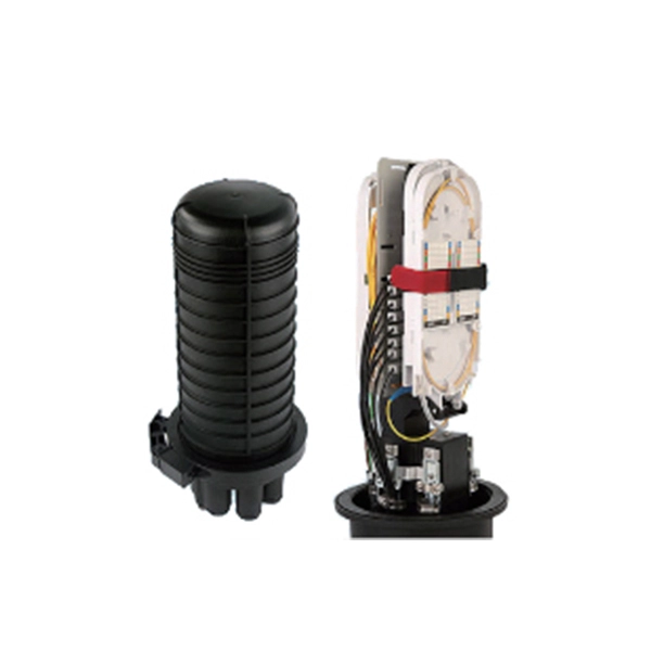
What does a 72-core optical cable look like
GYTA53 fiber cable consists of 250um fibers held in gel-filled PBT loose tubes, and wrapped around a phosphatized steel wire central strength member. A waterproof compound fills the loose tube, and the center of the cable core is a metal reinforced core. 72 core fiber optic cable should be selected by fiber standard, cable structure, jacket, tensile strength, installation route, drum length, testing, and quantity. single mode GYTA53 fiber optic cable and multimode. Fibertronics' Fiber Optic Distribution Cable is composed of high quality colored tight buffers, aramid yarn and a PVC outer jacket. Their small bend radius allows for fast installations and easy terminations within confined. Corning ribbon plenum cables are designed for use in plenum, riser and general purpose environments for intrabuilding backbone installations and for high-fiber-count data centers.
[PDF Version]
-
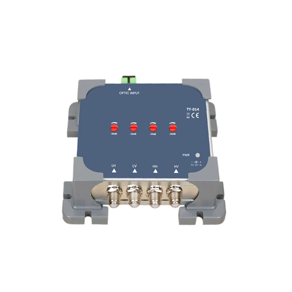
Fiber optic cable connected to router then connected to switch
If using a network switch with SFP ports, insert the fiber optic transceiver into the SFP port and connect the fiber optic cable to the transceiver. Connect the other end of the Ethernet cable to your network device, such as a computer, router, or. Fiber Optic Transceiver: Often used with media converters or network switches, these devices convert electrical signals to optical signals and vice versa. Patch Panel. As we speak I just have optic fibre (Community Fibre) connected to my Huawei modem / Linksys Velop which will be connected to a new POE switch (need to identify the best model to be compatible with my optic fibre extension project). Network topology refers to the way in which the links and nodes of a network are arranged in relation to each other. Use a standard Ethernet cable (Cat5e/Cat6) to.
[PDF Version]
-
Optical cable channels are divided into
The light signal is divided into multiple channels with different frequencies and wavelengths, each transmitting a different data stream. In general, the fiber cable link system will be more secure if the fewer fiber cable segments. This region occupies a bandwidth of 95nm or 11THz! 8 cn cor where L is the fiber length, c is the speed of light, and ncor and nclad are the core and cladding refracitve indexes, respectively. Why not always use SMF? Optical phase information is lost in the detection process. What is a wavelength? What are optical wavelengths? What are nominal. In telecommunications, frequency-division multiplexing (FDM) is a technique by which the total bandwidth available in a communication medium is divided into a series of non-overlapping frequency bands, each of which is used to carry a separate signal. It essentially consists of a data transmitter, a transmission fiber (in some cases with built-in fiber amplifiers), and.
[PDF Version]
-

Single-mode port connected to multimode fiber optic cable
Single mode and multimode fiber cables are quite different when it comes to size, light source, signal, and so on. So, they definitely are not interchangeable, and compatibility issues can occur when you try to connect a single mode fiber optic connector to a multimode network. This is where fiber conversion comes in. Single-mode. To realize the short-range direct connection to the end B switch with the same port, the same 10GBASE-SR SFP+ module should be plugged into the end B switch port. What if end B is located in. It's possible because Multi-mode optical cables have a very wide fiber core – 62. Understanding the key differences between these two technologies is essential for IT professionals, business owners, and even homeowners looking to future-proof their network.
-
What is a fiber optic cable with a connector called
The fiber connector types, sometimes referred to as terminations, link fiber optic cables together through terminals, switches, adapters, and patch panels, by bridging the gap between their internal glass fibers that transmit the data down the length of the cable. An optical fiber connector is used to join optical fibers where a connect/disconnect capability is required. They come in various types like SC, LC, ST, and MTP, each designed for specific. The fiber connector is called a fiber optic or optical fiber connector.
-

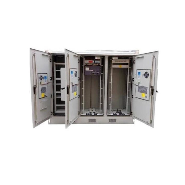
Do cables have to be run in cable trays
Answer: Yes; cables are tied down in cable trays to keep the cables in the cable tray, to maintain spacing between cables, or to segregate or confine certain types of cables to specific locations. The last two items can also be accomplished with a solid fixed barrier. Cable tray types, fill rules for single-conductor and multiconductor cables, ampacity derating, separation requirements, and when to use tray vs conduit. Cable tray is the preferred wiring method for industrial facilities, data centers, and large commercial buildings where routing dozens or. Cable tray barriers can be used to separate conductors operating over 600 volts from other conductors in the same tray operating at 600 volts or less. Code Change Summary: A clarification was made regarding separation of conductors in cable trays when conductors operate at different voltage levels. This is a description of how to select, install, and support these metal or plastic frames, on which electrical wires are installed. You should consider it as a series of instructions that make the buildings resistant to. Article 392 of the NEC provides the basic requirements for installations using cable tray.
[PDF Version]
-
Installation of galvanized plastic cable trays
This guide covers the critical steps, from selecting the right electrical cable tray and performing accurate cable fill calculations to managing a safe cable pull through and ensuring all bonding and grounding requirements are met. Are you looking for a cost-effective and durable solution for organizing and protecting your cables? Look no further than cable tray galvanized. But before you lay the first tray or clamp down a single cable, you need a solid plan. This guide breaks down the process step by step. The selection of material and finish is a function of the environment in wh tant in a wide range of environments, and easily formable (Appendices II and III). The process described here takes a systematic approach to ensuring that cable tray installations meet safety, reliability, and project-specific needs while following to. Method Statement installation of Cable Trays and Ladders - Planning Engineer FZE.
[PDF Version]
-
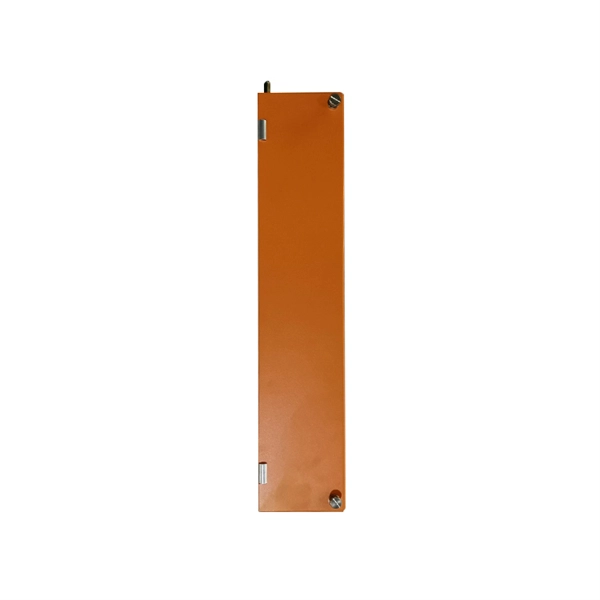
Fiber optic cable outer sheath representation
1 The outer cable jacket shall be marked with the manufacturer's name, date of manufacture, fiber count, fiber type, flame rating, listing symbol, and sequential length markings every two feet (e., “CORNING OPTICAL COMMUNICATIONS OPTICAL CABLE - MM/YY. XXXXX (feet. One important consideration when selecting indoor fiber optic cables is the outer sheath material and its fire prevention level. Each cable is single packed in a polybag with a test report that guarantees best performance in typical application scenarios like telecommunication, rack cabling, sensor technologies or indust Choosing the appropriate outer sheath material for fiber optic cables is crucial for ensuring the cable's durability, protection, and performance under specific environmental conditions. At the same time, it must have. 1. 1 The cable shall meet all requirements stated in this specification. Glass fiber and plastic fiber is fragile.
[PDF Version]
-
Metrology Standards for Cable Tray Supports
The International Electrotechnical Commission (IEC) provides detailed guidelines for cable tray systems under IEC 61537. This standard outlines the construction requirements, testing methods, and performance parameters for cable trays and related support systems. Covers construction and test requirements for. Cable tray systems provide a safe, organized, and flexible method for supporting insulated conductors and cables in commercial and industrial electrical installations. When properly selected and installed, cable trays simplify routing, improve accessibility, and support future expansion while. us-trations without notice.