-
List of Congo optical cable protection units
This is a list of international. It does not include, such as those on the coastlines of,, and. All the cable systems listed below have in two or more countries. Several older cables are no longer used for international telecommunications, but are used for scientific purposes. Others are simply abandoned.
-

Relay Protection Circuit Diagram Numbering Rules
This handbook covers the code of practice in protection circuitry including standard lead and device numbers, mode of connections at terminal strips, colour codes in multicore cables, dos and donts in execution. Also principles of various protective relays and schemes including special protection. For power grid systems, ANSI and IEEE functional number codes dictate the use and restrictions of both the devices themselves, as well as the functions of those devices within the scope of a circuit. These devices include switches, disconnects, circuit breakers, generators, and motors. One is given in ANSI Standard and uses a numbering system for various functions. The functions are supplemented by letters where amplification of the function is required.
-
Is relay protection a high-voltage system
Protective relaying is the backbone of fault detection and system isolation in high voltage (HV) power networks. As transmission systems grow increasingly complex with integration of renewables and smart technologies, the design, configuration, and application of protective relays have become more. The article provides an overview of protective relaying principles and their applications for high-voltage power system components. It covers the protection methods for generators, transformers, buses, and transmission lines using various relay types to detect and isolate faults efficiently. The relays are in round glass cases. This prevents damage to equipment, reduces downtime, and safeguards.
-
What is the relay protection time difference
The IEC standard for relay coordination recommends time grading between relays based on fault current magnitude and operating characteristics. For overcurrent protection, a minimum time margin of 0. 5 seconds is often maintained between primary and backup relays. The principle is to grade the operating times of the relays in such a way that the relay closest to the fault spot operates first. In order for the relay to operate, it needs to be energized. This energy can be provided by battery sets (mostly) or by the monitored circuit itself. In which case you use any of them. Are there any benefits of using one. A protection relay is a crucial component of electrical systems that safeguard infrastructure, employees, and equipment from electric problems and malfunctions. The relay settings that are selected are often a compromise in order to cope with both overload and. In electrical engineering, a protective relay is a relay device designed to trip a circuit breaker when a fault is detected.
[PDF Version]
-
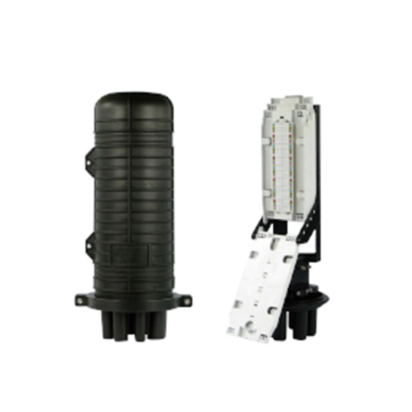
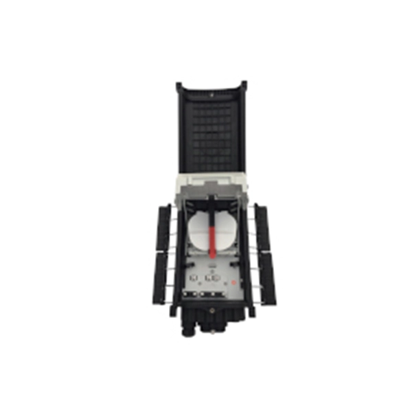
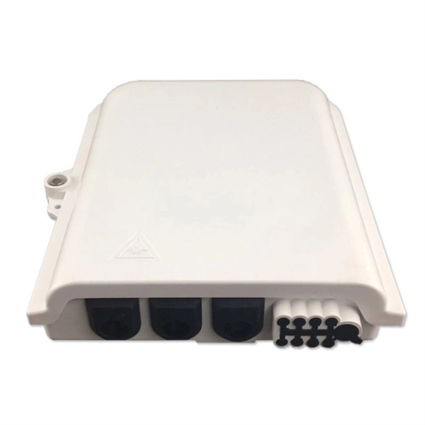
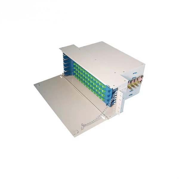
The function of the fiber optic cable protection box
They provide a secure, organized, and stable environment for the sensitive points within a fiber network—splices, connectors, and distribution points—safeguarding them from a multitude of external threats. For any organization deploying or maintaining a fiber network, understanding the role and. Fiber Connection Protection Box is a device designed for fiber optic line terminal connection and protection and is widely used in fiber optic communication systems such as fiber to the home (FTTH), local area network (LAN), and metropolitan area network (MAN). Its main functions can be summarized as follows: 1. Fiber closure protects spliced fibers in backbone and feeder lines, fiber box (or fiber distribution box) organizes and splits fibers in.
-
The first microprocessor-based relay protection system
Schweitzer, III, invented the first microprocessor-based digital protective relay. The SEL-21 was the culmination of research done for Schweitzer's doctoral thesis, and it ushered in a new era of power system protection and went on to revolutionize the electric. In 1982, Edmund O. Schweitzer was born in. Curtiss-Wright's Nuclear Division has partnered with Schweitzer Engineering Laboratories (SEL) to serve as a channel to market for SEL's line of digital protective relays and engineering services for Commercial Nuclear markets worldwide. These relays operated based on mechanical movement, with components like coils, springs, and armatures working together to detect abnormalities in the electrical system.
-

Optical cable protection structure includes
Optical fibers have small cross sectional areas. Cable structure includes buffers, strength members, and jackets. What are fiber optic cables made of? A fiber optic cable consists of five basic components: the core, the cladding, the coating, the strengthening fibers, and the cable jacket. When searching for a fiber optic cable, we need to pay attention not only to the connectors, such as SC to ST fiber cable. An optical fiber cable is a complex structure designed to protect fragile glass fibers that transmit digital data using light signals. This advanced cabling solution allows fast, secure data transfer and telecom over long distances. This course describes multimode and single mode step-index and graded-index fibers. Cable provides protection for the optical fiber or fibers within it appropriate for the environment in which it is installed. You will also learn how different aspects of the product can affect budget and design.
[PDF Version]
-

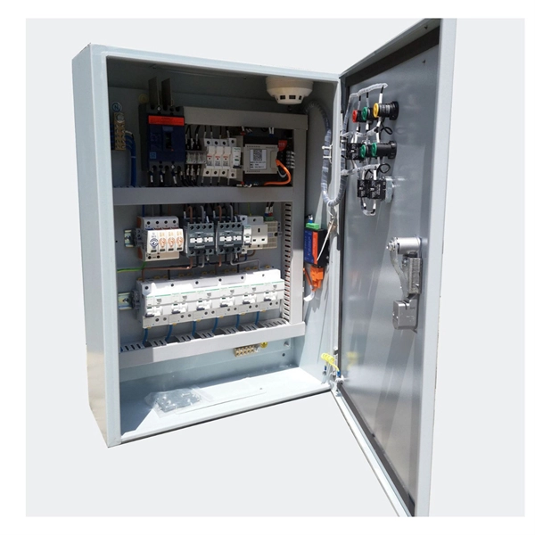
Distribution Box Protection Method
Its primary purpose is to ensure safe and efficient power distribution while providing protection via fuses or circuit breakers against overloads and short circuits. Distribution boxes are built with durable materials, typically metal or high-grade plastic, designed to endure. EPRI has been exploring protective device configuration approaches tar-geted at minimizing the chances of adverse interactions with the power system and the environment. More specifically, electrical faults caused by vegetation, animals, conductor slap, lightning and equipment failures can each. A distribution box, also known as a power distribution box or electrical distribution box, is used to distribute electrical power safely to multiple circuits. Circuit Breakers or Fuses: These safety devices automatically stop the flow of electricity during faults or overloads. Fuses melt when too much current. Electrical systems power our homes, offices, and industrial facilities, but behind every reliable electrical setup lies a crucial component that often goes unnoticed: the distribution box.
[PDF Version]
-

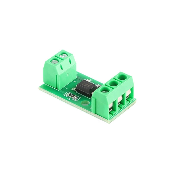
Relay Protection Test Wiring Method
One approach to test the total protection system is to use primary injection techniques (see appendix H) that trigger protective relays and lockout relay, trip circuit breakers, and initiate annunciations and indications. If applicable, documentation is required detailing how verified protection segments overlap to ensure there is not a gap. The purpose of this Standard Work Practice (SWP) is to standardise and describe the method for testing of Ergon Energy protection relays for commissioning purposes. This SWP should be interpreted in conjunction with Standard for Substation Protection (V1. From a technician's perspective, master the unique skill of testing protection. When the transformer wiring type is Y/Y (Y0), the test wiring is very simple: when testing phase A, the tester IA is connected to the phase A of the high voltage side, and the tester IB is connected to the phase a of the low voltage side. After the neutral line of the high and low voltage sides is. Function: Use electronic components like transistors to perform switching. Applications: Frequency, undervoltage, and overcurrent protection.
[PDF Version]
-
Wired Channel for Relay Protection
With the addition of a line tuner, the CCVT (used for potential input to the protective relay) can be used to couple the PLC signal to the power line. Protection systems are used to isolate faulted parts of the system, protect the electric system from instability, and minimize equipment damage. Directional distance and overcurrent schemes, interfaced with communication equipment, send and receive logic-based information between relay te minals to determine if the fault is external or internal to the. Important benefits include limiting tripping to faulted line section, high-speed simultaneous clearing for all internal line faults, preventing overtripping on external faults, and reducing transmission line and station damage. Applications of the concepts to accepted transmission line-protection schemes are also presented.
-

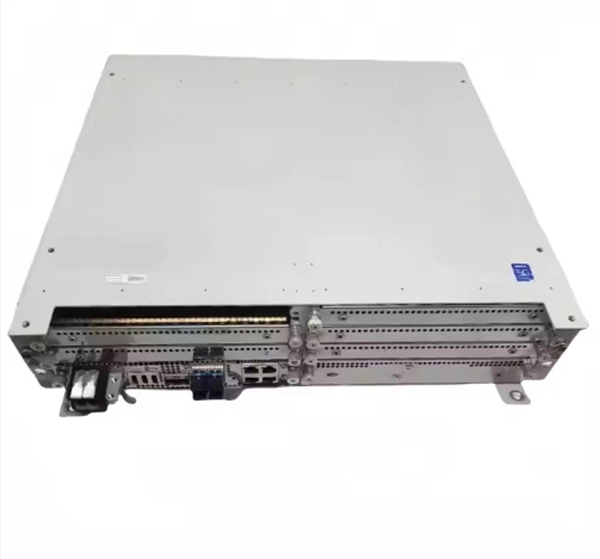
Circuit Breaker Relay Protection Equipment Model
Microprocessor-based solid-state digital protection relays now emulate the original devices, as well as providing types of protection and supervision impractical with electromechanical relays.OverviewIn, a protective relay is a device designed to trip a when a is detected. The first protective relays were electromagnetic devices, relying on coils operating on moving par. Electromechanical protective relays operate by either, or. Unlike switching type electromechanical with fixed and usually ill-defined operating voltage thresholds. Electromechanical relays can be classified into several different types as follows: "Armature"-type relays have a pivoted lever supported on a hinge or knife-edge pivot, which carries a moving contact. These relays may.
-
Requirements for Relay Protection Design
The IEEE standard for protection relays refers to a collection of guidelines developed by the Institute of Electrical and Electronics Engineers. This document provides recommendations, background and philosophy on relay protection that is not available in M07. They are intended to quickly identify a fault and isolate it so the balance of the system continue to run under normal conditions. For professionals working in utilities, industries, or renewable energy systems, understanding these standards is not optional—it is essential. This handbook covers the code of practice in protection circuitry including standard lead and device numbers, mode of connections at terminal strips, colour codes in multicore cables, dos and donts in execution.