-

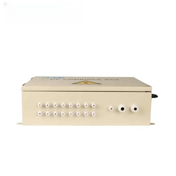
Lightning Protection Parameters for Photovoltaic Combiner Boxes
Technical Parameters:DC voltage shall not be lower than the system's highest voltage; circuit breaking capacity shall be at least 20kA to ensure that a faulty bypass is disconnected in 0. 1 seconds in the event of a short circuit. Summary: Discover how intelligent combiner boxes with lightning protection optimize photovoltaic system safety, reduce downtime, and improve ROI. Learn about critical components, industry trends, and why EK SOLAR's solutions stand out in global markets. Lightning strikes cause 7–12% of all. When selecting a photovoltaic (PV) combiner box, several key parameters must be considered to ensure the efficient operation and safety stability of the PV power station. This device plays a vital role in safeguarding solar installations from.
-
Six-Column Relay Protection Tester
Specifically designed for settings-based protection testing with a high degree of automation, our modular software Test Universe offers numerous functions and application-optimized test modules that save yo.
-

Relay Protection Test Wiring Method
One approach to test the total protection system is to use primary injection techniques (see appendix H) that trigger protective relays and lockout relay, trip circuit breakers, and initiate annunciations and indications. If applicable, documentation is required detailing how verified protection segments overlap to ensure there is not a gap. The purpose of this Standard Work Practice (SWP) is to standardise and describe the method for testing of Ergon Energy protection relays for commissioning purposes. This SWP should be interpreted in conjunction with Standard for Substation Protection (V1. From a technician's perspective, master the unique skill of testing protection. When the transformer wiring type is Y/Y (Y0), the test wiring is very simple: when testing phase A, the tester IA is connected to the phase A of the high voltage side, and the tester IB is connected to the phase a of the low voltage side. After the neutral line of the high and low voltage sides is. Function: Use electronic components like transistors to perform switching. Applications: Frequency, undervoltage, and overcurrent protection.
[PDF Version]
-
Is it dangerous to repair relay protection
Doing so may result in reducing Relay performance for insulation failure, contact welding, and contact faults, and might even result in burning or other damage to the Relay itself. Do not drop the Relay or dismantle it. Refer to the Safety Precautions for individual Relays for precautions specific to each Relay. Electric shock may. A relay that is correctly set for yesterday's system may become a serious risk after a plant expansion or load change. This article breaks down the most common protection relay misconfigurations in industrial facilities, why they happen, and how they impact system reliability and operational. onding to faults, ensuring the reliability and stability of the grid. However, unauthorised changes to protection relay settings pose a significant threat to the integrity of power systems. Although failure of a protective relay system may have severe local or regional impacts, most protective relay systems are not required to operate to prove they are in working order.
[PDF Version]
-

Busbar Connector Protection Box Usage
It is mainly used for insulation protection and safety protection of busbar connections in switchgear factories, power plants, and substations. In modern industrial electrical distribution systems, busbar systems serve as the backbone for power distribution, channeling electricity from main sources to various circuit protection devices and loads. The connection between molded case circuit breakers (MCCBs) and busbars represents a critical. The busbar joint protection box is made of radiation cross-linked polyolefin material. It has excellent physical, chemical and electrical properties. The high magnitude fault currents require high-speed. DEFINITIONS.
-
What is ARD in relay protection
The AR/ARD relays are electromechan-ical convertible contact relays. Earlier relays do not necessarily incorporate all the features described. The Delta ARD4 User Guide is designed as a. Smart Motor Protector ARD2 Series (hereinafter referred to as Protector) utilizes advanced single chip technology and is featured in the strong anti-interference, stable and reliable running, digitalization, intelligence and networking. The protector can protect the motor from timeout startup. The ARD3M intelligent motor protector is suitable for low-voltage motor circuits with rated voltage up to 660V and integrates protection, measurement, control, communication, operation and maintenance. AR. Shop Now ARD Series Motor Protection Relay.
-

What is the highest voltage rating of relay protection instruments
High voltage relays are used in many technical devices that require voltages that go up to 10,000 V and currents up to 30 A. Elko HRN-43N Three Phase Monitoring Voltage Relay (with neutral) for 3x400V circ. Various dc models provide protection of battery and UPS systems and a range of temperature protection products is ideal to prevent the damaging effects of overheating. They operate using the same basic principles as electromechanical relays, but include features designed to allow use in high voltage applications. The maximum rating is 600VDC. The normally closed contact is rated 10 amps continuous. We are guided by our commitment to do business right, world's most urgent power management challenges.
-
Relay protection panel reset
Operate the mechanical reset lever or pushbutton on the lockout relay, or use the relay's HMI/SCADA interface for electronic relays. For microprocessor relays, use the front panel or remote interface to acknowledge and reset the lockout/trip condition. In this comprehensive guide, we will delve into the essential steps for resetting a relay efficiently and effectively. From troubleshooting common issues to performing the reset process step-by-step. How can I reset the Alarm or Trip on 857 Motor protection relay? There are two status indicators named "Alarm" and "Trip" on the front panel that is mapped within the Output Matrix. #relay #lockoutrelay #electrical #howtoresetrelay #86relay #mastertriprelay lockout relay function lockout relay wiring diagram lockout relay 86 protection lockout relay wiring lockout relay operation lockout relay 86. View all of Eaton's protective relays PowerPort-E can not connect to the device. The settings in a 751 shouldn't be reset because of a loss of power.
[PDF Version]
-
Relay Protection Inspection and Acceptance
This guide explores the different types of protection relays and their testing procedures, with a focus on tools like secondary injection test sets and three-phase relay test sets. To properly test relays, understanding their classification by design and application is. The testing and verification of relay protection devices can be divided into four groups: Type tests are needed to prove that a protection relay meets the claimed specification and follows all relevant standards. These are not repeated unless incorrect operation occurs. Although failure of a protective relay system may have severe local or regional impacts, most protective relay systems are not required to operate to prove they are in working order.
-
Factors affecting relay protection
Other Factors: Springs losing resiliency, poor contact alignment, open coils, improper ratings, and physical damage can also break a relay. Proper selection, usage, and maintenance can help prevent these issues. One of the most common causes of relay failure is overloading and. Previous experience in designing low voltage and medium voltage switchgear, relay panels and custom control panels as an Electrical Engineer at ESSMetron, Denver CO. Graduated with a Master of Science in Electrical Engineering from The University of Texas at Dallas in 2018 and with a Bachelor of. The selected protection principle affects the operating speed of the protection, which has a significant im-pact on the harm caused by short circuits. The calculation of relaying load limits for use in comparing to transmission line load limits or other limits is discussed. This document provides recommendations, background and philosophy on relay protection that is not available in M07. This text aims to provide an.
[PDF Version]
-
The first microprocessor-based relay protection system
Schweitzer, III, invented the first microprocessor-based digital protective relay. The SEL-21 was the culmination of research done for Schweitzer's doctoral thesis, and it ushered in a new era of power system protection and went on to revolutionize the electric. In 1982, Edmund O. Schweitzer was born in. Curtiss-Wright's Nuclear Division has partnered with Schweitzer Engineering Laboratories (SEL) to serve as a channel to market for SEL's line of digital protective relays and engineering services for Commercial Nuclear markets worldwide. These relays operated based on mechanical movement, with components like coils, springs, and armatures working together to detect abnormalities in the electrical system.