-

Principles and Product Design of Optical Fiber Communication
Optical Fiber Communication (OFC) revolutionizes modern telecommunications, enabling rapid data transfer across long distances with minimal signal loss. This comprehensive review explores OFC's historical evolution, core principles, components, and versatile applications. Kanade Department of Electronic-Science, P. College of ASC, Pravaranagar, India fPublished. The digital communication techniques discussed so far have led to the advancement in the study of both Optical and Satellite communications. Light acts as a carrier wave and can be modulated to carry information. Higher bandwidth (extremely high data transfer rate).
-
Optical Module Base Design
Optical module usually consists of a transmitter assembly (TOSA, containing a laser LD chip), a receiver assembly (ROSA, containing a photodetector PD chip), a driver circuit, an optoelectronic interface, a heat sink (some models), a housing, a pull ring and so on. Integrated circuits and reference designs help you create a smaller and faster optical module design used in high-bandwidth data communication applications. Whether you are creating a 100-Gbps or 400-Gbps, small form-factor pluggable (SFP) module, SFP+ transceiver, XFP module, CFP, X2/XENPAK module. Designing and producing these complex PCBs presents formidable challenges, requiring a convergence of disciplines—from high-frequency signal integrity and advanced thermal management to micron-level mechanical precision. These three laser diodes are described in more detail. contact us product page Copyright © 2024 MVSLINK. Critical Metrics: Signal integrity (insertion loss, return loss) and thermal management are the two.
[PDF Version]
-
WDM Fiber Optic Communication System Design
This lesson demonstrates the basic features of a typical WDM optical communication system and shows the basic design steps with OptiSystem. The performance of the system will be shown and compared. In fiber-optic communications, wavelength-division multiplexing (WDM) is a technology which multiplexes a number of optical carrier signals onto a single optical fiber by using different wavelengths (i. Single mode fiber is favored over Multimode fiber for long-distance communication. Firstly, the WDM optical. While fiberoptic technology resulted in a significant increase in a network's "bandwidth," or the amount of information that the network could send, tbe creation of the Internet resulted in an even greater demand for bandwidth. As demand for network capacity increased, service providers exhausted.
-
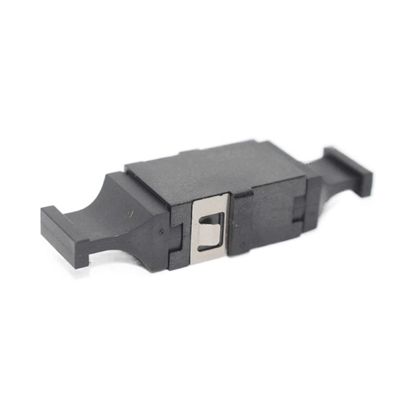
MEMS optical switch design
In figure 1.2 a row of protection switches is shown that is used in parallel optical connections (e.g. bus connections between computers). All channels have to be switched at the same time to reroute the signals from one computer to ano. In figure 1.2 a row of protection switches is shown that is used in parallel optical connections (e.g. bus connections between computers). All channels have to be switched at the same time to reroute the signals from one computer to another. Protection switching is required to avoid a permanent interrupt of a connection due to fiber break or due to. mirror / shutter surface micromachining Si-On-InsulatorElectromagnetic actuators are used in optical switches, as these actuators are known from precision machined solutions and the actuating part is a simple coil of many turns of wire. The ferromagnetic materials required in microsystems can easily be realized by sput-tering or electroplating of Permalloy. Additionally, the combination of permanent ma.
[PDF Version]
-
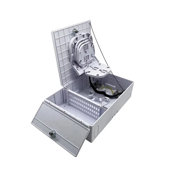
How to coil the fiber optic cable at the end of the optical fiber
For overly long or short fibers, coil them separately at the end. Before fiber coiling, the optical cable and pigtail should be pre-processed, and the optical cable and pigtail should be opened first. The key step is to calculate the reserved length and then splice the optical fiber. The success rate of optical fiber splicing is very important, because once the. Splice fiber optic cables follows these steps: stripping, cleaving, splicing, and coiling. When done right, splicing ensures minimal loss and long-lasting performance. This guide will walk you.
-
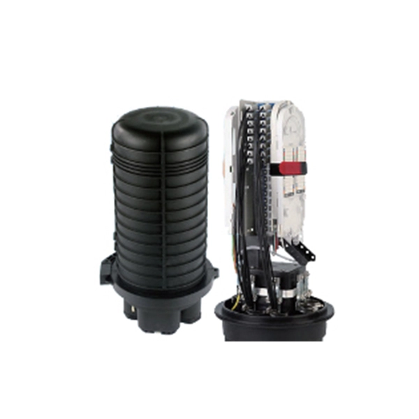
How to coil the pigtail together
After one end of the pigtail has been connected to your device, use lineman's pliers to twist together the bare end of the pigtail wires with the circuit wires, turning in a clockwise direction. A pigtail is composed of three strands of wire. Drunk posting ill conceived instructables since 2009. Here is a super-easy way permanently coil a cable such as a USB, Lightning, or similar data / charging cable. In this video, I demonstrate how to make a mechanically and electrically sound pigtail splice. When twisted properly, they maintain consistent power distribution while isolating faults. Imagine three wires needing to.