-
1-meter wide cable tray support spacing
Generally, standard trays require supports every 6 to 10 feet, while heavy-duty, long-span trays can handle distances of up to 20 feet between supports. To determine the proper spacing, consult the manufacturer's load capacity chart, which accounts for the total weight of the. The NEC requires that cable trays must be supported by members at an interval specified by the cable tray manufacturer, but not more than 5 feet for horizontal runs to support the weight of the cables and other loads. The NEC has a requirement for ladder-type cable trays. The rungs cannot be more. en completely installed, without damage either to conductors or structural system use maintain spacing or to keep cables in place when the tray is ect the minimum bend ra-dius for cables as they exit the bottom of the cable tray. Proper installation can significantly reduce electromagnetic interference, prevent fire hazards, and improve overall efficiency. This article provides an in-depth. Ladder cable tray is available in widths of 6, 9, 12, 18, 24, 30, 36, 42 and 48 inches with rung spacings of 6, 9, 12 or 18 inches. The Ladder Tray features light, rugged, tubular steel construction.
[PDF Version]
-
Optical Module Lens Design
Looking to learn about optics and optical design? Learn the basics of optics needed to begin designing optical systems in this educational, online Fundamentals of Optics course co-created by E.
-

KVM Switcher Recommendations
The first step to finding the right KVM switch is taking inventory of what you'll use it with: specifically, the number of computers, monitors, and additional peripherals, such as a keyboard and mouse. Yo.
-
Elevator cable tray support spacing
Support spacing for cable trays must align with the manufacturer's instructions, as outlined in NEC 392. Generally, standard trays require supports every 6 to 10 feet, while heavy-duty, long-span trays can handle distances of up to 20 feet between supports. Specifiers should be aware that some cable tray. Understanding cable tray spacing is key to meeting safety regulations and maintaining system performance. The spacing between trays, whether horizontal or vertical, depends on various factors like cable type, environment, and tray material. The Ladder Tray features light, rugged, tubular steel construction. 50 in the development and approval of the document at the time it was developed.
-
Spacing of cable tray supports inside electrical wells
The NEC requires that cable trays must be supported by members at an interval specified by the cable tray manufacturer, but not more than 5 feet for horizontal runs to support the weight of the cables and other loads. The NEC has a requirement for ladder-type cable trays. Cable trays are used for supporting. Article Summary: A compliant cable tray installation requires a thorough understanding of NEC Article 392, proper structural support, and precise installation techniques. These systems, made from metal or plastic, are open structures designed to support electrical conductors, ensuring proper organization and safety. Cable tray is the preferred wiring method for industrial facilities, data centers, and large commercial buildings where routing dozens or. maintain spacing or to keep cables in place when the tray is ect the minimum bend ra-dius for cables as they exit the bottom of the cable tray. A rung spacing of 6 to 9 inches (150 to 230 mm) is preferable when the cable tray cont d for instrumentation and control applications that require.
[PDF Version]
-
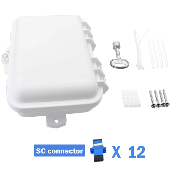
Spacing between communication optical cables and power cables
The National Electrical Code establishes specific minimum distances when communications cables must run near power and light circuits. This practice is mandatory for two distinct reasons: ensuring the safety of the structure and its occupants, and preserving the integrity of sensitive data. Maintaining proper separation between power, data, and limited energy cabling is foundational to system performance, safety, and code compliance. Cable design and placement are very important to ensure that electromagnetic interference (EMI), or dangerous levels of electrical energy are not induced into. (12 in) between fiber optic communications cables lashed to a steel messenger located in the communication space and power company neutral conductors located in the supply space? A third party attacher has placed new, 1⁄4 in, galvanized steel strand and lashed dielectric fiber optic communications. FIGURES.
[PDF Version]
-
Spacing of vertical shaft cable tray fixing supports
Cable Management Tray Size: Choose a tray size that will hold the desired amount and length of cable. Support Spacing: Remember the NEC requires no more than 4 feet of support spacing. The National Electrical Code is a set of principles designed to promote public safety and welfare, as well as safeguard public health by regulating the design and operation of electrical facilities and. Article Summary: A compliant cable tray installation requires a thorough understanding of NEC Article 392, proper structural support, and precise installation techniques. This guide covers the critical steps, from selecting the right electrical cable tray and performing accurate cable fill. maintain spacing or to keep cables in place when the tray is ect the minimum bend ra-dius for cables as they exit the bottom of the cable tray. Proper installation can significantly reduce electromagnetic interference, prevent fire hazards, and improve overall efficiency. Clause 522-08-04 Where conductors or cables are not supported.
[PDF Version]
-
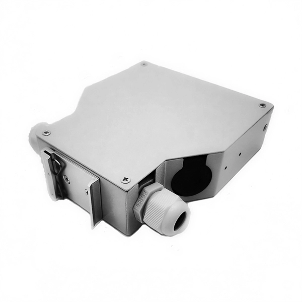
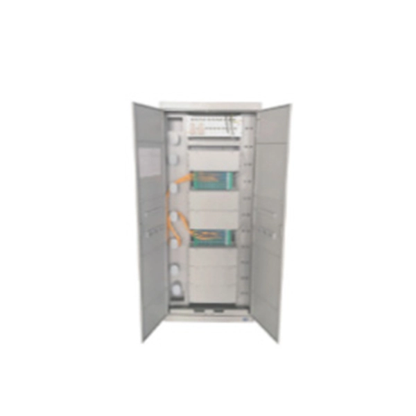
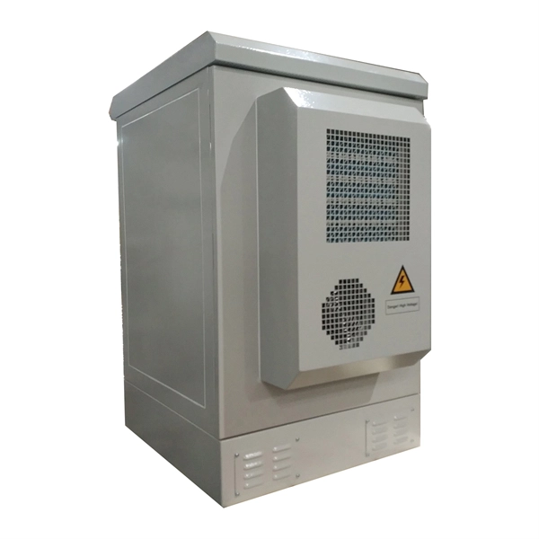
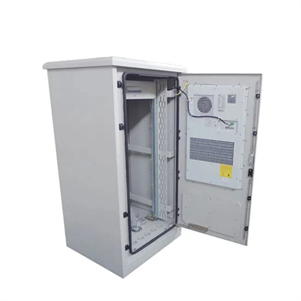
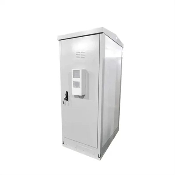
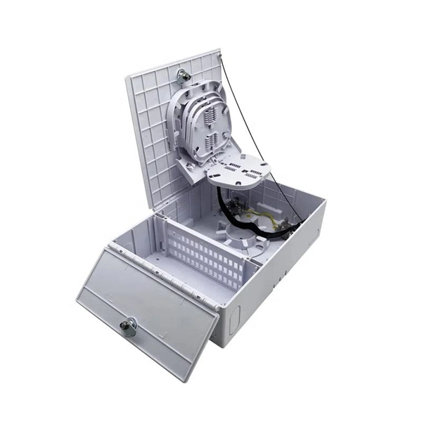
Spacing of the side of the distribution box
Side clearance: There should be a minimum of 30 inches of clearance from the sides of all electrical equipment, but in no case less than the width of the equipment itself. This is referred to as the side-to-side working space. In industrial power distribution systems, cable distribution boxes (also known as power distributor boxes, distribution electrical boxes, or electrical power distribution boxes) are the core hub of power transmission, branching, and protection. Its layout directly affects the efficiency of the. NEC Article 314 establishes requirements for the installation and use of electrical boxes, conduit bodies, fittings, and handhole enclosures. NEC Article 408. Boxes distribute low currents in an area equipped with 1 to 12 RJ 45 sockets. They centralise connections to ensure flexibility and that the installation is up to date.
[PDF Version]
-
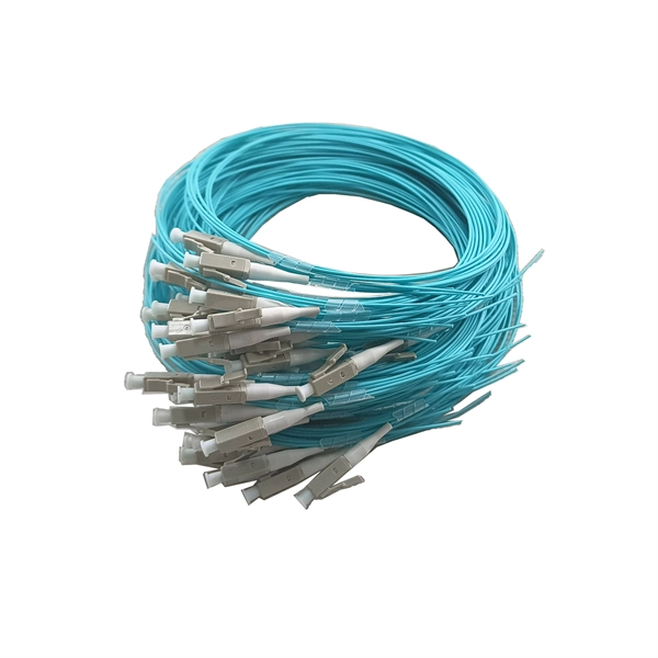
Fiber optic cable design reserve length
Standard/default length is 2 inches (reference), as produced by most label manufacturers. Marking details are based on MIL-STD-130 and will be legible and permanent. • Fiber optic cables are often custom cut to match required lengths for each cable run, or you can order a reel matching your total length and cut segments yourself. It's advisable to include a safety buffer when ordering, with an additional 10% being common practice, despite careful measurement of. Fiber optic network design refers to the specialized processes leading to a successful installation and operation of a fiber optic network. To calculate teh total number of fiber strands that will be required for the fiber optic cable installation, many people makes the mistake of underestimating the total. All lengths are calculated in a base unit, then converted. Reel count is ceil (Total ÷ ReelSize), and the rounded order length equals Reels × ReelSize. (FOA) was founded in 1995 to help develop the workforce to build the fiber optic networks to support a rapid expansion in communications and the Internet.
[PDF Version]
-
MEMS optical switch design
In figure 1.2 a row of protection switches is shown that is used in parallel optical connections (e.g. bus connections between computers). All channels have to be switched at the same time to reroute the signals from one computer to ano. In figure 1.2 a row of protection switches is shown that is used in parallel optical connections (e.g. bus connections between computers). All channels have to be switched at the same time to reroute the signals from one computer to another. Protection switching is required to avoid a permanent interrupt of a connection due to fiber break or due to. mirror / shutter surface micromachining Si-On-InsulatorElectromagnetic actuators are used in optical switches, as these actuators are known from precision machined solutions and the actuating part is a simple coil of many turns of wire. The ferromagnetic materials required in microsystems can easily be realized by sput-tering or electroplating of Permalloy. Additionally, the combination of permanent ma.
[PDF Version]
-
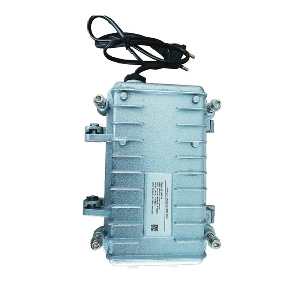
Optical Module Base Design
Optical module usually consists of a transmitter assembly (TOSA, containing a laser LD chip), a receiver assembly (ROSA, containing a photodetector PD chip), a driver circuit, an optoelectronic interface, a heat sink (some models), a housing, a pull ring and so on. Integrated circuits and reference designs help you create a smaller and faster optical module design used in high-bandwidth data communication applications. Whether you are creating a 100-Gbps or 400-Gbps, small form-factor pluggable (SFP) module, SFP+ transceiver, XFP module, CFP, X2/XENPAK module. Designing and producing these complex PCBs presents formidable challenges, requiring a convergence of disciplines—from high-frequency signal integrity and advanced thermal management to micron-level mechanical precision. These three laser diodes are described in more detail. contact us product page Copyright © 2024 MVSLINK. Critical Metrics: Signal integrity (insertion loss, return loss) and thermal management are the two.
[PDF Version]