-
10kV Busbar Voltage Testing Standard
IEC 61439 is a standard developed by the International Electrotechnical Commission (IEC) that covers design verification for low-voltage electrical products and assemblies. The IEC 61439. 7 cycles of 24 h each to salt mist test according to IEC 60068-2-11; (Test Ka: Salt mist), at a temperature of (35 ± 2) °C. The test shall be carried out according to IEC 60068-2-2 Test Bb, at a temperature of 70 °C, with natural air circulation, for a duration of 168 h (7 days) and with a recovery. ULTRUS™ helps companies work smarter and win more with powerful software to manage regulatory, supply chain and sustainability challenges. Consistent performance benchmarking testing capabilities for professional PC users. Award-winning software and advisory services for ESG management and. The purpose of this method is to verify the functionalities of a Metal Enclosed Busb ar. How do you check and maintain busbars? What are the faults of busbar? What is bus bar in DB? For complete safety instructions and precautions, always refer to the test equipment instruction manual.
[PDF Version]
-

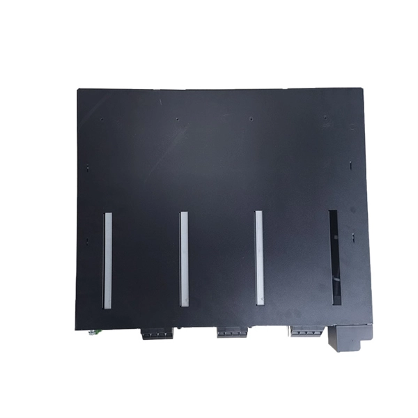
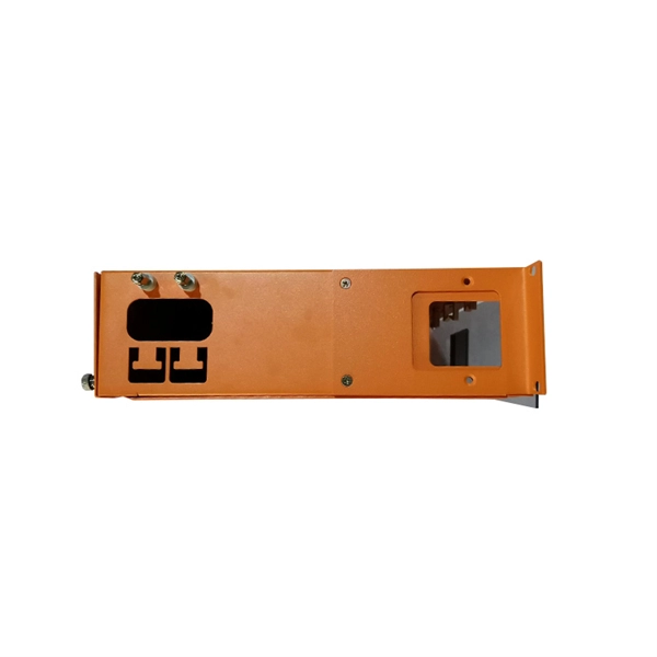
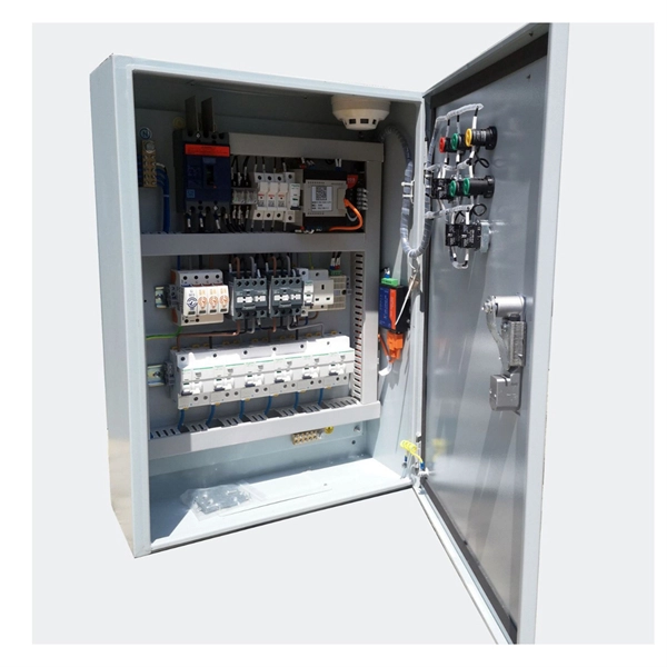
Internal Components of the Distribution Box for Low Voltage Electrical Systems
A low voltage distribution box features robust enclosures, busbars, and protection devices to ensure safe, efficient power distribution in electrical systems. This. Inside, you'll find parts like circuit breakers and fuses that protect the system from problems like overloads and short circuits. These critical components house essential elements, including circuit. Will the Internal Spacing and Gaps Affect the Safety of the Distribution Box? What Is a Distribution Box? The distribution box can also be called a distribution board or an electrical panel. Through my years working with electrical.
-
What is the standard for all-dielectric optical cable
This standard covers the construction, mechanical, electrical, and optical performance, installation guidelines, acceptance criteria, test requirements, environmental considerations, and accessories for a nonmetallic, all-dielectric self-supporting (ADSS) fiber optic. This standard covers the construction, mechanical, electrical, and optical performance, installation guidelines, acceptance criteria, test requirements, environmental considerations, and accessories for a nonmetallic, all-dielectric self-supporting (ADSS) fiber optic. tic cable are covered by this standard. The ADSS cable is designed to be located p trical and Electroni s Engineers, Inc. mportant notices and legal disclaimers. * Note: Corning recommends storing. AFL-ADSS® (All-Dielectric Self-Supporting) cable is ideal for installation in distribution as well as transmission environments, even when live-line installations are required.
[PDF Version]
-
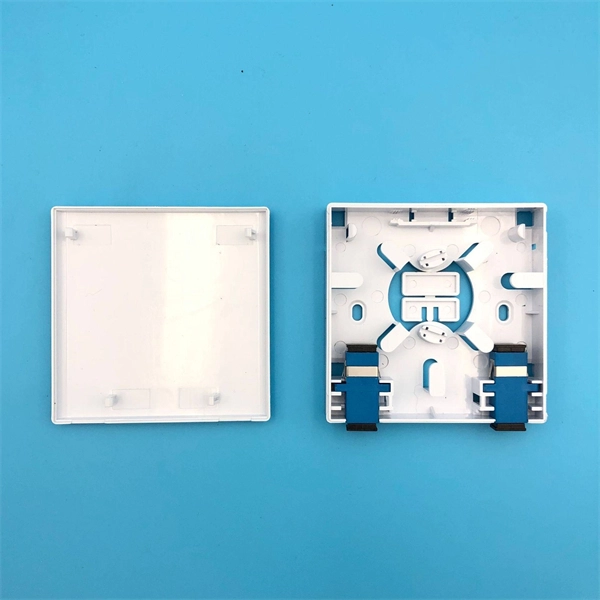
Standard rack fiber optic cable fixing
Excavate the cable at the break point and use a fiber optic cutter to remove the damaged section. Superior server rack cable management is imperative with today's data center packed to capacity with a mix of equipment. Start with proper planning: Moreover, we'd better consider planning for installing. Proper fiber management inside rack and wall mount enclosures is vital for maintaining reliability, protecting delicate optical connections, and ensuring your network infrastructure remains easy to service. We are a local business based in San Jose specializing in communication. At Bay Lan Communications, we are committed to establishing long-term customer relationships by consistently exceeding expectations and becoming a partner in your growth through our outstanding services. As a leading structured cabling and fiber optics company Bay Lan Communications assures. The Fiber Optic Association, Inc.
[PDF Version]
-
Calculation Standard for Optical Cable Blocking Costs
TIA-568 Standard: The Telecommunications Industry Association (TIA) publishes TIA-568 standards that specify maximum connector loss (0. 75 dB) and cable specifications for fiber optic installations. Buying fiber optic installation services involves several cost components, with total price influenced by length, location, and access. The main cost drivers include trenching or aerial deployment, materials, labor hours, and any required permits. This guide presents typical price ranges in USD to. Optical Link Budget is the maximum allowable signal loss between a transmitter (Tx) and a receiver (Rx) in a fiber optic link. Here's a general pricing reference: Cable TypePrice Range (USD/meter)Simplex / Duplex Indoor Cable$0. These cost data are obtained directly from a variety of sources.
-
Standard for the Reserved Length of Cables in Distribution Boxes
The NEC outlines clear rules for how much wire should be left in an electrical box. For any outlet, junction box, or switch point where a connection or splice will be made, there must be at least six inches of free conductor. A coil of cable at a box is not required by code but it might make things easier on future repair work. Code Change Summary: Revised code language on supporting Nonmetallic Sheathed Type NM cable. A conduit body is a removable-cover section of a conduit system that provides access at junctions or termination points. The box capacity table shown (page A-5) is reproduced in part from the NEC® as a quick reference and. For any professional aiming for a C-10 license or working in commercial construction, Understanding NEC Article 314: The Protocol is a core technical requirement. Cable sizing methods do differ across international standards (e.
[PDF Version]
-
WDM Fiber Optic Communication System Design
This lesson demonstrates the basic features of a typical WDM optical communication system and shows the basic design steps with OptiSystem. The performance of the system will be shown and compared. In fiber-optic communications, wavelength-division multiplexing (WDM) is a technology which multiplexes a number of optical carrier signals onto a single optical fiber by using different wavelengths (i. Single mode fiber is favored over Multimode fiber for long-distance communication. Firstly, the WDM optical. While fiberoptic technology resulted in a significant increase in a network's "bandwidth," or the amount of information that the network could send, tbe creation of the Internet resulted in an even greater demand for bandwidth. As demand for network capacity increased, service providers exhausted.
-
Requirements for Relay Protection Design
The IEEE standard for protection relays refers to a collection of guidelines developed by the Institute of Electrical and Electronics Engineers. This document provides recommendations, background and philosophy on relay protection that is not available in M07. They are intended to quickly identify a fault and isolate it so the balance of the system continue to run under normal conditions. For professionals working in utilities, industries, or renewable energy systems, understanding these standards is not optional—it is essential. This handbook covers the code of practice in protection circuitry including standard lead and device numbers, mode of connections at terminal strips, colour codes in multicore cables, dos and donts in execution.
-

Emergency Circuit Design for Distribution Boxes
Size emergency and standby circuits with NEC 700/701, IEC 60364-5-56, UPS/generator transfer paths, and real voltage-drop examples. On a recent plan review, the riser looked clean: NEC 700 emergency lighting, a listed transfer switch, copper conductors, and breakers sized. Emergency and standby power systems are designed to provide an alternate source of power if the normal source of power, typically the electric utility service, should fail. Reliability of these types of systems is critical and good design practices are essential. Classification of Emergency and. Emergency system circuits supply power to critical life safety loads such as emergency lighting, fire alarm systems, fire pumps, smoke control systems, and essential communication and control circuits. Correct wiring design for emergency system circuits is essential to maintain power integrity. The National Electrical Code (NEC) Section 700. Under no. Another is to limit what qualifies as an “emergency load,” so the emergency system powers only what is needed to save human life (Fig.
[PDF Version]
-
Standard Requirements for Direct Burial Depth of Optical Cable Conduit
While local codes and soil conditions dictate specific requirements, general industry guidelines are: Standard Residential/Commercial Areas: 24 to 36 inches (60 to 90 cm) deep. However, simply hitting this depth isn't enough to guarantee your network survives. Factors like the. Estimate minimum burial depth (cover) for underground electrical, fiber, and low-voltage cable runs using a practical, code-aware ruleset. 5 underground burial depths is essential for passing inspection and ensuring a safe installation. Under Roadways or Driveways: 36 to 48 inches (90 to 120 cm) deep, often within a conduit for added protection. 8 million km in scope by 2025 (per TeleGeography), burying these cords of light comes with the benefits of avoiding cable damage, decreasing downtime, and extending their operational lifetime. But how deep is fiber optic cable buried?Underground fiber optic cable installation follows specific standards that govern burial depth, testing methods, installation techniques, and safety requirements. These standards, established by organizations like the National Electrical Code (NEC), National Electrical Safety Code (NESC), and.
[PDF Version]
-
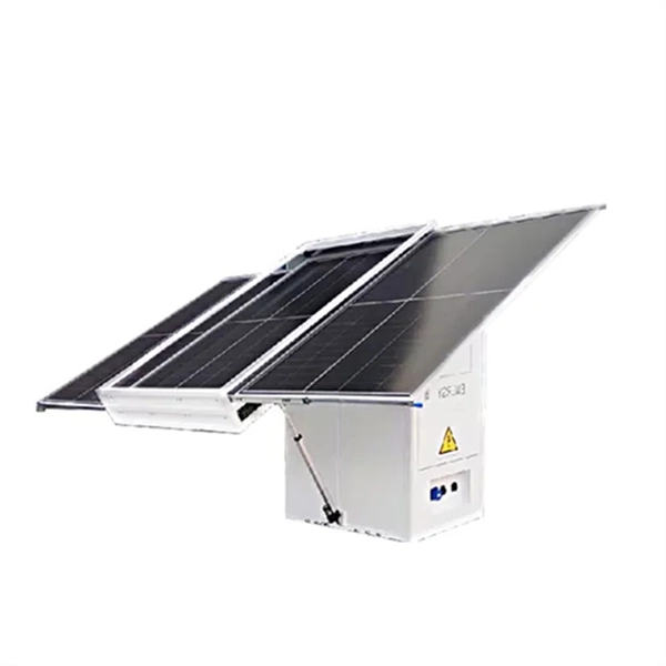
Photovoltaic combiner box ISO standard
IEC 62548: This standard specifically addresses design requirements for PV arrays, including detailed specifications for combiner boxes. ance cables by combining strings at the array locat ciency, reliability and safety in solar energy systems. They enable centralized management in large-scale and remote installation ity), equipment aging, and poor installation practices. Additionally, it facilitates efficient execution of regular. A solar combiner box is a crucial component in solar energy systems, designed to consolidate the outputs of multiple solar panel strings into a single output that connects to an inverter. Eaton (Bussmann) understands that no two PV installations are alike and that the. Often misunderstood by novices as a simple "junction box," a commercial-grade combiner box is, in reality, the most critical safety barrier and diagnostic hub located between the photovoltaic array and the inverter.
[PDF Version]