-
Standard Requirements for Busbar Connection Distance
The IEC standard for busbar clearance plays a critical role in the design and safety of electrical panels and power distribution systems. Key technical considerations include: 1. These clearances help prevent arcing, short circuits, and. Undersized busbar spacing is not a cosmetic defect. Dielectric tests, power frequency withstand for all voltages and impulse withstand for medium voltage, are specified in the standards. The design must pass these tests.
-

Standard for Grounding Resistance of Directly Buried Optical Cables
101 describes characteristics, construction and test methods of optical fibre cables for buried application. Note that Recommendation ITU-T L. This Applications Engineering Note (AE Note) discusses conventional bonding and grounding practices for conductive fiber optic cable and hardware installations within the scope of the National Electrical Code (NEC). First, in order to demonstrate sufficient performance of an. Section 250. (FOA) was founded in 1995 to help develop the workforce to build the fiber optic networks to support a rapid expansion in communications and the Internet. Keywords:acceptance testing, cable, cable installation, cable selection, communication cable, electrical. study of this important article.
-
10kV Busbar Voltage Testing Standard
IEC 61439 is a standard developed by the International Electrotechnical Commission (IEC) that covers design verification for low-voltage electrical products and assemblies. The IEC 61439. 7 cycles of 24 h each to salt mist test according to IEC 60068-2-11; (Test Ka: Salt mist), at a temperature of (35 ± 2) °C. The test shall be carried out according to IEC 60068-2-2 Test Bb, at a temperature of 70 °C, with natural air circulation, for a duration of 168 h (7 days) and with a recovery. ULTRUS™ helps companies work smarter and win more with powerful software to manage regulatory, supply chain and sustainability challenges. Consistent performance benchmarking testing capabilities for professional PC users. Award-winning software and advisory services for ESG management and. The purpose of this method is to verify the functionalities of a Metal Enclosed Busb ar. How do you check and maintain busbars? What are the faults of busbar? What is bus bar in DB? For complete safety instructions and precautions, always refer to the test equipment instruction manual.
[PDF Version]
-
Low-voltage busbar current carrying capacity standard
For busbar sizing, the primary references are IEC 61439 (for low-voltage switchgear and controlgear assemblies) and IEC 60287 (for current-carrying capacity of cables). IEC 61439 is a standard developed by the International Electrotechnical Commission (IEC) that covers design verification for low-voltage electrical products and assemblies. Special service conditions, for example in ships and in rail vehicles provided that the other relevant specific requirements are complied with. Current load capacity is the maximum value of the current flowing through the conductor in an unlimited period of time in certain conditions – it will.
-
How to ground the busbar of the switchgear
Bus bar grounding can be achieved by one of two methods: grounding clamps applied to bus bars or a separate switchgear section with a switching mechanism dedicated to ground. In most assemblies you will find horizontal main bars, vertical risers, neutral and equipment-ground buses, and purpose-designed. The purpose of this manual is to assist the user in developing safe and eficient procedures for the installation, maintenance and operation of the equipment. For additional information, refer to NEMA Standards Publication PB2. Dive in to power up your knowledge! These guidelines govern the busbar processing and installation procedures. With the exception of SF6-to-air bushings terminals, all active portions of gas-insulated switchgear (GIS) are contained within grounded enclosures, which means that they are not susceptible to inadvertent contact. This makes gas-insulated switchgear intrinsically safe. In addition, numerous. New Approaches for Maintenance Grounding in Medium-Voltage Switchgear by Joe Richard and David Mabius Executive summary Maintenance grounding has traditionally been performed by maintenance personnel working in close proximity to open switchgear.
[PDF Version]
-

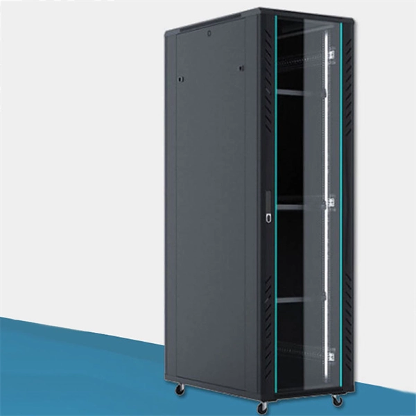
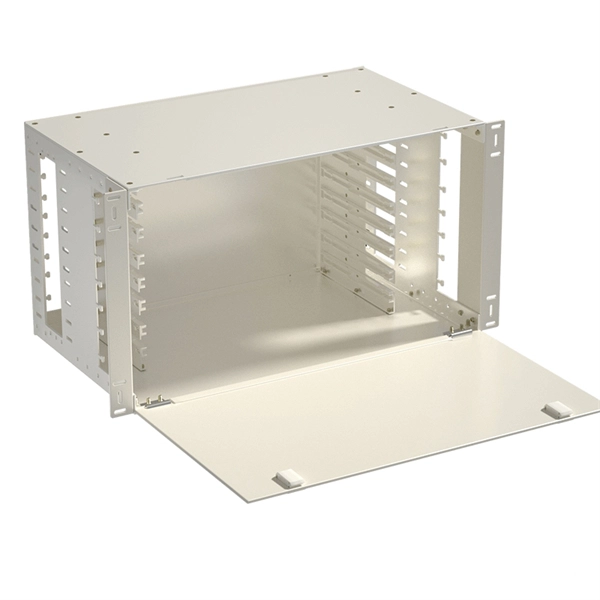
Switch cabinet busbar installation
In North America, follow UL 891 construction and NEC Article 408 installation practices: use listed/approved hardware, lugs, or tap-off provisions intended for the bus. The matrix below helps engineers finalize material, arrangement, plating/insulation, and verification. The GRL busbar system makes distribution cabinet installation fast, flexible, and neat. At this stage, the supports have been installed in accordance with the installation plan. Ever wondered how busbars, the unsung heroes of electrical distribution, are processed and installed? This article delves into the intricate steps of busbar selection, preparation, and installation, ensuring efficient and safe power distribution. The application of these rules means strict compliance, not only with applicable regulations and standards, but also with manufacturers'. Bus bars play a crucial role in electrical distribution systems by providing a reliable and efficient way to conduct electricity within electrical panels.
[PDF Version]
-

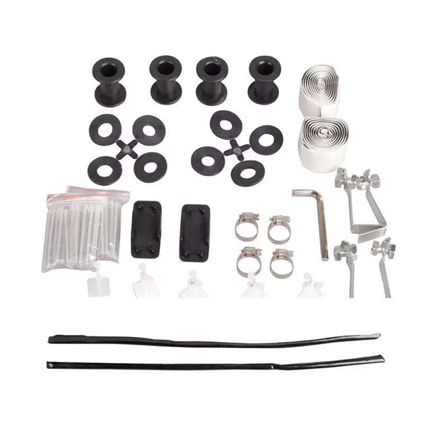
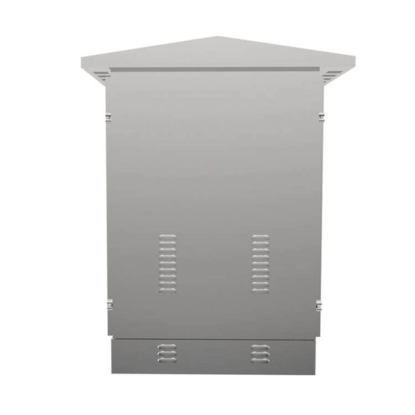
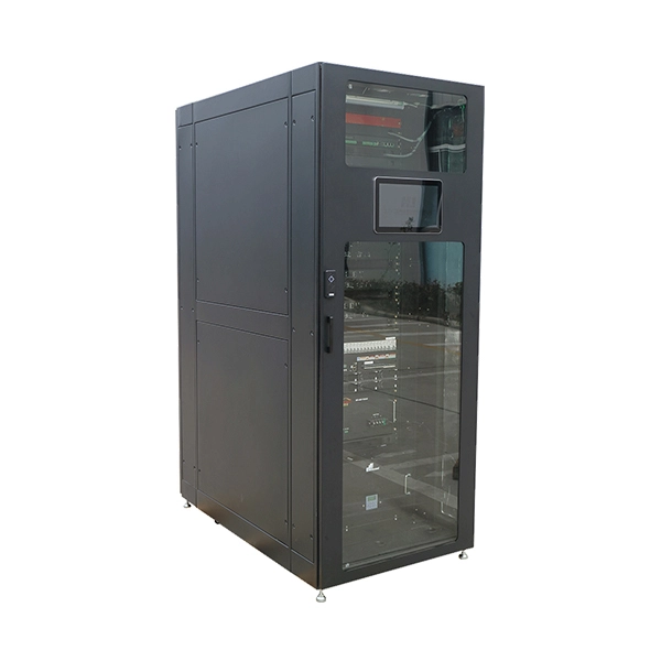
El Salvador Broadcast Transmission Busbar Wall-Mounted
Electrical busbar systems (sometimes simply referred to as busbar systems) are a modular approach to, where instead of a standard cable wiring to every single electrical device, the electrical devices are mounted onto an adapter which is directly fitted to a current carrying. This modular approach is used in, panels and other kinds of installation in an electrical enclosure.
-
35kV busbar protection time
Operating time of any tripping protection relays must be added to this time, however an overall tripping time of less than two cycles can be accomplished. With high-speed circuit breakers, total fault clearance may be obtained in roughly 0. Common methods of protecting busbars include overcurrent-based interlocking schemes, overcurrent-based differential protection, high-impedance differential protection, and percentage differential protection. Interlocking and overcurrent differential protection can be implemented with any suitable. This specification applies to three-phase, [select #] - way [select # -source, select # -tap], 50-60 Hz, fully dead front, sectionalizing underground distribution switchgear; with maximum main bus rating of [select: 200 or 600] amperes continuous current and maximum tap rating of [select: 200 or. In principle, busbar protection is needed when the system protection does not protect the busbars, or when, in order to keep power system stability, high-speed short circuit current clearance is needed. Unit busbar protection meets these requirements. Also, in the case busbars sections are. A FAULT IN A BAY BETWEEN A CB AND A CT.
[PDF Version]
-
The 10kV busbar has been changed from maintenance to operation
There are many standards on the subject pertaining to different voltage levels of switchgear, which normally defines four separate aspects of maintenance, with each new stage based on the preceding one, 1. Inspection, 2. Servicing, 3. Examination and 4. Overhaul. These are dealt with in detail below:Maintenance covers a wide range of activities, all of which are required to keep the switchgear in ready condition at all times to enable it perform its functions satisfactorily. The parts subjected to normal wear and agingneed to be serviced for ensuring full reliability of the operations. These parts may be mechanical components or electrical com. Safety features need to be planned before switchgear units are ordered. The requirement of locking off parts of the system (for carrying out maintenance work on the associated plant) should be finalised. Proper interlocking arrangements should be provided for this purpose. All metal-enclosed switchgears are designed so that all live conductors are.
[PDF Version]
-

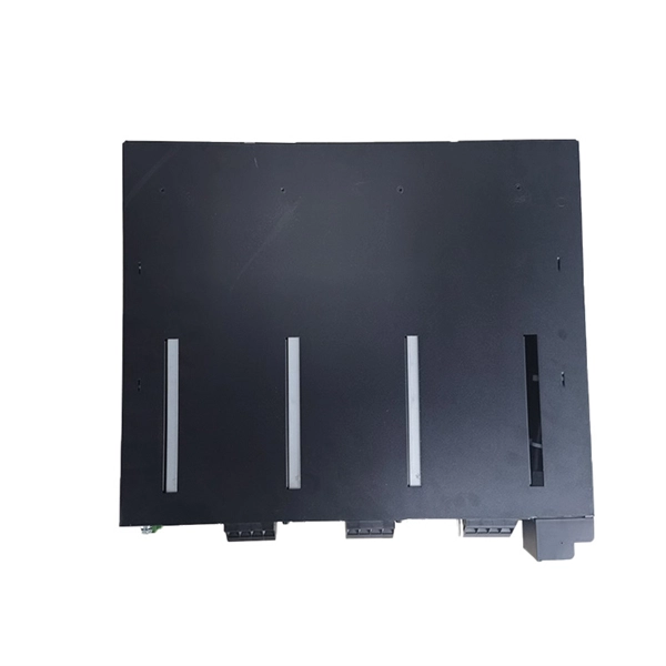
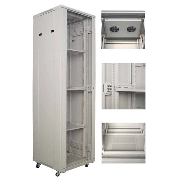
Mns switchgear busbar compartment height dimensions
Independent main busbar compartment is on the top part which is separated from the device compartment. In no event shall ABB be liable for direct, indirect, special, incidental, or consequential damages of any nature or kind arising from the use of this document, nor shall ABB be liable for incidental or consequential damages arising from use of any software. The MNS R frame is based on modular 2 mm thick still C sec-tions, pre-drilled at a pitch of 25 mm. The switchgear is pre set for easy extensions on both sides. The ends are designed to allow installation of future sections. With a rated voltage of up to 1000 V AC or 1500 V DC and a rated current of up to 6300 A, it offers exceptional performance and reliability. This together with the global service and support network established in over 30 manufacturing locations world wide ensures that the choice of MNS® will be the EC 61439 -1/2.
[PDF Version]
-
Why should the power supply to the small busbar be disconnected
To protect the bus from faults, it is mandatory to disconnect it from all the power sources as soon as possible. This means that, breaker CB-1, 2, 3 & 4 must open during actuation of busbar protection. You might think that only CB-1 should open. Busbar protection is a protection scheme meant to protect the busbar from electrical fault. Double Busbar arrangement or one and half breaker scheme. With increasing short-circuit power in the network. Disadvantages: Single bus-bar system has the following three principal disadvantages:- The bus-bar cannot be cleaned, repaired or tested without de-energizing the whole system. Thus, it is an electrical junction where all incoming and outgoing currents connect. Always use appropriate personal protective equipment, such as safety glasses and insulated gloves, and verify circuits are dead using a multimeter.
[PDF Version]