-
Which company should I choose for flame-retardant optical cables in smart buildings
Plenum fiber optic cables are suitable for use in areas where the air is circulated and fires are difficult to control, so OFNP flame-retardant fiber optic cables are the best choice. Flame resistant cable may be deployed in-duct (conduit) or cable tray. When routing a cable within a building, you will also need to factor in fire prevention. These composite cables are specifically designed for radiation sensors and to withstand harsh environments encountered in nuclear power plants. As a manufacturer, we know that the chemical composition of the cable jacket (Plenum, Riser, or LSZH) is the most expensive part of the production BOM.
-
Laying optical cables on the road
The document outlines steps like obtaining permissions, excavating trenches, laying ducts, providing additional protection, backfilling trenches, and performing optical tests after installation. This article gives an overview of this technology, which enables road-surface wiring by installing optical-fiber cables in grooves formed on asphalt pavement. Light signals traveling through a pure glass core offer significantly greater bandwidth and signal integrity, making it the preferred choice for connecting distant buildings. 4. FO-VC2 JOINT USE - VERICAL MIDSPAN CLEARANCES 48. RF W8P04C – cable. The Fiber Optic Association, Inc. (FOA) was founded in 1995 to help develop the workforce to build the fiber optic networks to support a rapid expansion in communications and the Internet. Before starting the installation, it is important to keep.
[PDF Version]
-
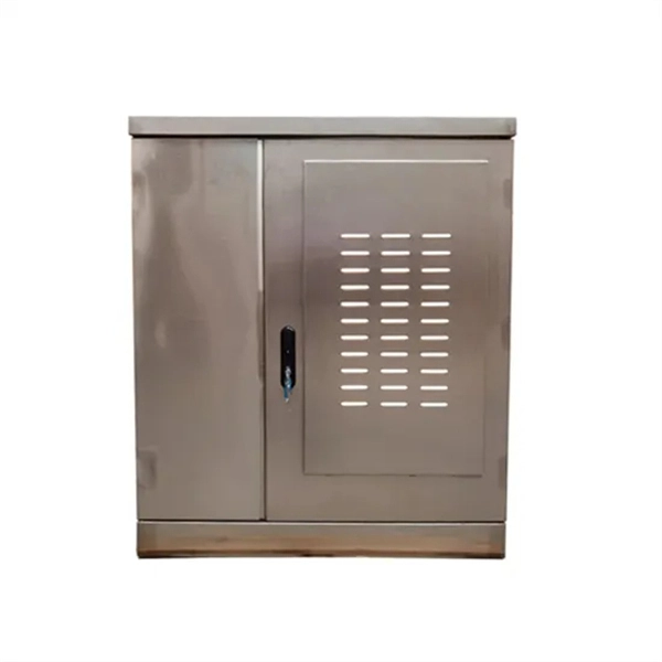
Where should the cables be run through the network cabinet
For network cable routing, it's also necessary to pass through the upper cable holes of the cabinets, with preference for the side of the cable trays closer to the cold aisle. The aim is a secure, maintainable and scalable operation of the network environment. In this guide, we'll walk you through everything you need to know. In order to meet the normal operation of these devices in the cabinets, when the computer room cabinets are full of various cabinets and devices, we need to consider how to place the network cabinets? 1. Network cabinet placement skills (1) Before. Data centers, organizations and schools consists of server racks and network cabinets in the IT departments to support an abudance of data cables, power cords and network devices. Different TYPES OF SERVER RACKS.
-
What are the uses of special optical cables in the field
While standard fiber optic cables serve well in general communication networks, specialty cables offer unique features, such as enhanced performance in extreme environments, increased data capacity, or compatibility with specific wavelengths of light. At its most basic, a fiber optic cable is composed of glass threads (optic fibers), each of which can transmit messages. Optical fibers have transformed how we communicate, connect, and transmit data. Among these, special optical fibers stand out for their tailored properties, enabling applications beyond traditional telecommunications. As technology advances, the demand for specialized optical cables has grown, leading to the development of various specialty fiber cables. HOC (Hone Optical Communications) special fiber optic cable means the optical cables used in special areas or need special structure and materials to meet the application environment. It is designed to transmit data in the form of light signals over long distances with minimal signal loss.
[PDF Version]
-
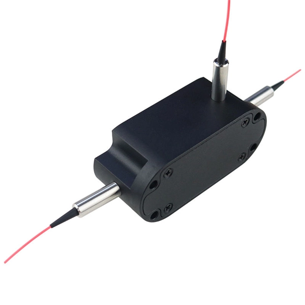
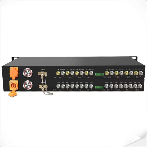
How to connect optical cables to split them into multiple paths
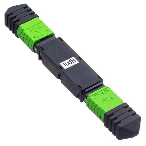
Optical couplers can split or join signals in fibers. These devices work both ways, which helps strong network communication. For example, optical splitters send light to many output ports. You can also use them to join light from. Before attempting to split a fiber optic cable, gather the necessary tools and equipment: Fiber Optic Splitter: This device divides a single optical signal into multiple signals. It typically consists of an MPO connector on one end, which can accommodate multiple fibers, and multiple connectors (such as LC or SC) on the other end, each. Optical splitters offer a cost-effective and dependable solution across various fiber optic applications. Also known as optical splitters, fiber splitters, or beam splitters, these devices are integrated waveguides ensuring wide bandwidth and minimal loss in high-frequency applications. This device takes the incoming light signal and divides it into multiple paths, allowing the signal to be sent to multiple devices.
[PDF Version]
-
Cables without armor are run in cable trays
The cables identified as Type TC-ER (Exposed Run) can be installed in industrial establishments for the connections between the cable trays and the equipment without metal conduits or armored cables Type MC (Metal Clad Cable); this kind of connections is called Open Wiring. Type TC – Tray Cable – (NEC Article 336) –Power and control tray cable type TC is a factory assembly of two or more insulated conductors, with or without associated bare or covered grounding conductors, under a non-metallic jacket. Pictured here are:. UL Listed shielded cables (THHN/THWN or TFN) built for the uses specified by art. 336 of ANSI/NFPA 70 “National Electrical Code” (NEC) and suitable for use in Class I, Division 2, Hazardous Locations. 8 meters (6 ft) of cable extends from the tray for a connection to a motor or other electrical device, cables without an ER rating must be either armored (type MC) or installed in conduit or another. Tray cable types TC, ITC and PLTC are permitted in cable trays by the NEC. CEC 12-904 (2) indicates that no raceway shall contain conductors of a different source unless they have metal armor.
[PDF Version]
-
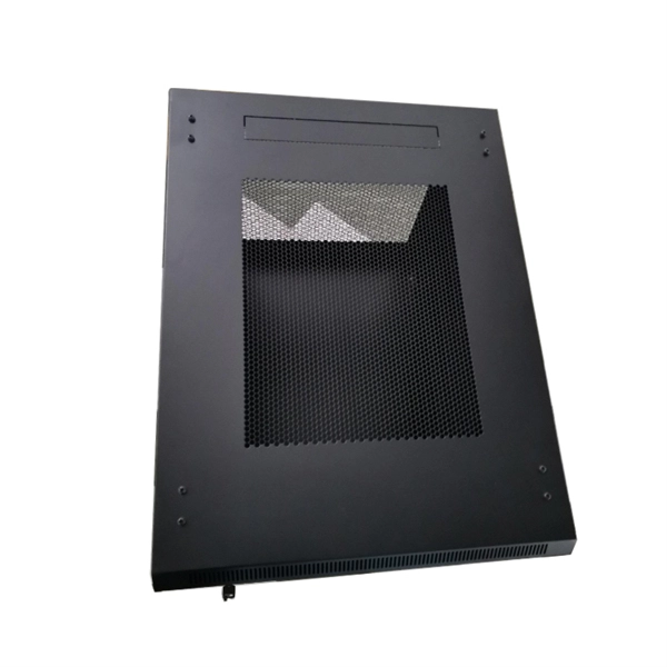
How to configure network cables in a network cabinet
Learn how to wire Ethernet cables using TIA/EIA standards, choose the right racks and cabinets, and organize cables with proper management systems for clean, reliable installations. One of the first steps in setting up a home network wiring cabinet is choosing the right location. Ideally, you'll want a central location in your home where you can easily access and manage your network equipment. This could be a closet, a utility room, or even a dedicated home office space. Welcome your inquiry! Website: www. Rack Elevation or Server Rack Layout Software are simple tools to plan and document the cabling of your server cabinet. To make it even easier for you, we launched the free online Rack. Effective network cable management transforms chaotic server rooms into streamlined, professional installations that enhance performance, reduce downtime, and simplify maintenance.
[PDF Version]
-
Function of cable tray pulleys for pulling cables
These pulleys reduce friction, minimize cable stress, and enhance safety during cable pulling and routing operations. Understanding their construction and functionality is crucial for optimal usage. Each part. The Cable Tray Pulley stands as a critical component, facilitating the smooth and damage-free installation of power, control, and communication cables across diverse applications. These specialized pulleys are engineered to support and guide cables during installation in cable tray systems. maintain spacing or to keep cables in place when the tray is ect the minimum bend ra-dius for cables as they exit the bottom of the cable tray. A rung spacing of 6 to 9 inches (150 to 230 mm) is preferable when the cable tray cont d for instrumentation and control applications that require. Proper cable tray installation improves system reliability, minimizes downtime, and ensures compliance with industry standards. Ø 140 mm, every project can be optimally implemented.
[PDF Version]
-
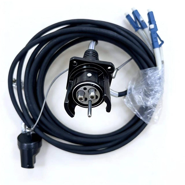
What materials are used for laying optical cables
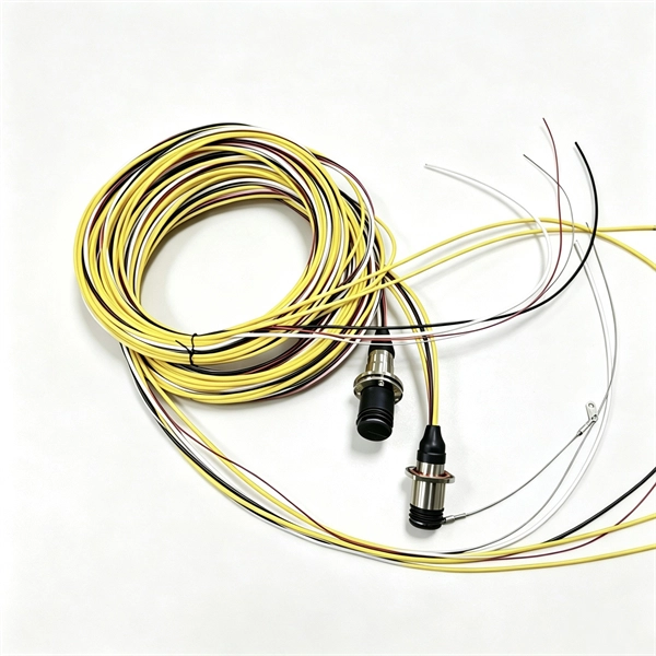
Each optical cable is constructed using a precise combination of optical fibers, strength members, buffer tubes, water-blocking elements, armoring, and protective jackets. Here is the extended technical table of all raw materials used in the fiber optic cable industry. The choice of material is an engineering decision driven by the need to. Fiber optic cables are designed to provide high-speed, no-signal-loss, and EMI-free communication in telecommunication, powergrid, datacenter, broadband, and industrial applications. This is where the magic happens – the core is designed to carry light signals over great distances with minimal loss.
-
What are the standards for laying trunk optical cables
This article introduces and explains the scope, application, and practical relevance of the eight most widely used fiber and optical cable standards: ITU-T G. 657, IEC 60793, IEC 60794, TIA-568. The Fiber Optic Association, Inc. The charter of the FOA was to promote professionalism in fiber optics through education, certification, and. Code (NEC) in effect at the time of publication. Because they are quality standards, NEIS® may in some instanc s go beyond the minimum requirements of the NEC. It is the responsibility of users of this standard to comply with state and local electrical codes s and improvements to this s 16. They define a minimum baseline of quality and workmanship for installing electrical products and systems. The following language is recommended: Fiber optic cables shall be installed in accordance with. Fiber optic networks are built on well-defined standards that ensure quality, performance, and interoperability.
[PDF Version]
-
How to assess the loss of optical cables
In optical fiber cabling, it is necessary to calculate the maximum loss on a certain length of the line. Calculation formula of optical fiber loss: The Total Link Loss = Cable Attenuation + Connector Loss + Splice Loss Cable Attenuation (dB) = Maximum Cable Attenuation. Loss in optical fiber, also known as fiber optic attenuation or attenuation loss, measures the amount of light loss from input to output. This loss can be caused by a multitude of factors, ranging from intrinsic material properties to environmental conditions. While some loss is expected, excessive or unexpected loss can lead to poor performance, network downtime, and signal failure. For more accurate measurements, use mode conditioning on the fiber near the source. There are many reasons for optical fiber loss, such as optical fiber material's absorption/scattering of light energy, bending. Fiber optic loss is one of the most fundamental parameters in optical network engineering, yet it is often misunderstood as a purely theoretical value used only during design calculations.
[PDF Version]