-
How to measure wear using fiber optic sensors
When the wafer dicing saw processes hard and brittle materials, the wear rate of the grinding wheel blade accelerates. To detect blade wear in time, a grinding wheel blade wear detection method based on a f.
-
How to inspect and maintain low-voltage complete sets of equipment
As needed, inspect and torque-test bolted electrical connections to the required values. Visual examination for overheating or degradation indicators. Examining each panel for rust and evidence of. How often should you inspect low voltage electrical equipment? What tools do you need for basic maintenance? Why is it important to keep maintenance records? Can you do maintenance yourself or should you call a professional? You help keep low voltage electrical equipment safe and working well. In this guide, you'll get a comprehensive checklist you can adapt to your facility so it remains safe and compliant at all times. The table below highlights common safety risks associated with. Preventive maintenance for low voltage switchgear is crucial for ensuring the reliability, safety, and longevity of electrical distribution systems.
-
How to label circuits during distribution box assembly
This application note provides a step-by-step guide for using a wire tracer to identify and label circuits in commercial buildings, ensuring safety, efficiency, and accuracy in your electrical work. Every home relies on a breaker box (also called a service panel or distribution board) to manage and protect its electrical circuits. Yet, one of the most overlooked steps in electrical safety and convenience is correctly labeling each circuit breaker. This makes fixing problems faster and keeps you safe. Use. The electrical panel, often called the breaker box, distributes power safely from the utility service to every outlet, light, and appliance. Every wire and circuit is managed here, making it the primary point for system control and safety.
-
How to Choose a Swiss Explosion-Proof Distribution Box
Explosion Proof Distribution Box & Electrical Enclosures are certified for Class I, Division 1 and Class II, Division 1. You need to check if the enclosure fits the danger level and protection type. For example, you might need Ex d for flameproof or Ex i for safe designs. In this article, we will explore three key aspects:. ·Flameproof enclosure (Ex db), which can be used as feed distribution equipment in control and distribution system (such as distribution box, switch box of main circuit, control box, terminal box or motor starting box etc. They prevent sparks, arcs, or high temperatures generated by internal electrical components from coming into contact with explosive gases or dust in the surrounding atmosphere. With a wide range of enclosure materials, sizes, ambient temperature ranges, and customizable configuration s, these solutions can. Options range from Ex d (flameproof enclosure) to Ex e (increased safety) and Ex i (intrinsically safe) right through to Ex p (pressurized housing), as well as combinations of different explosion-protection types – always bearing in mind the most efficient solution for your application.
[PDF Version]
-
How is the serial interface of the XFP optical module
The XFP 2-wire serial interface is used for serial ID, digital diagnostics, and certain control functions. It was defined by an industry group in 2002, along with its interface to other electrical components, which is called XFI. XFP modules can be installed or replaced in an Extreme Networks switch, I/O module, or router without powering off the system. All Extreme Networks XFP modules comply with. This Juniper Networks® XFP-10G-S compatible XFP transceiver provides 10GBase-SR throughput up to 300m over multi-mode fiber (MMF) using a wavelength of 850nm via an LC connector. It can operate at temperatures between 0 and 70C. The transceiver is compliant with CPRI, eCPRI. With these features, this 10G SFP+. ID systems defined for the GBIC and SFP transceivers. 12 document apply to Beta-and Production-level units only. Physical Medium Dependent (PMD) sublayer and baseband medium, type 10GBASE-S (short wavelength serial), 10GBASE-L (long wavelength serial), and.
[PDF Version]
-
How to connect the light wires to the secondary distribution box
To maintain the parallel connection, the incoming power wires must be spliced with the wires that connect to the first fixture and the new set of wires that will run to the second fixture box. This splicing is accomplished by using a technique called pigtailing. In this video, we'll walk you through the process of wiring a home distribution box with a detailed connection diagram. Single Phase Distribution Box generally consists of Double Pole MCBs, Single Pole MCBs, and RCCBs. How to wire an electrical junction box. A junction box is used to add a spur or to extend circuits and direct power to lights and additional sockets.
-
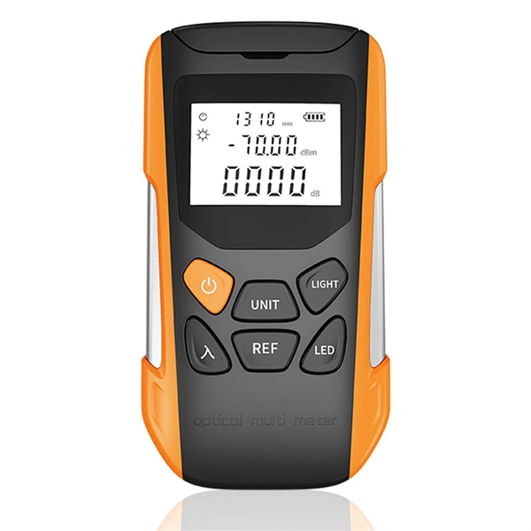
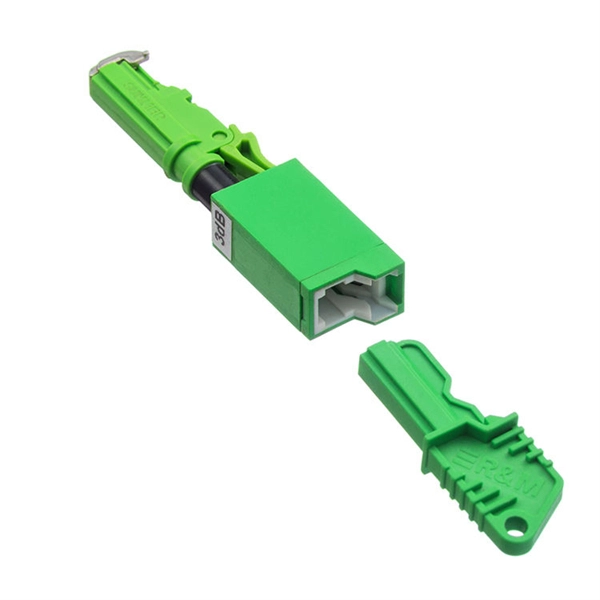
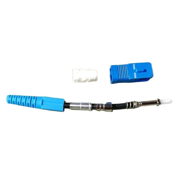
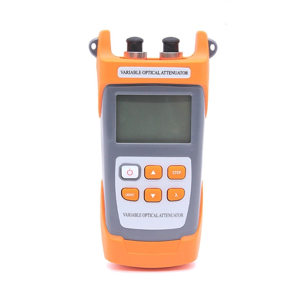
How to determine light attenuation of red light using an optical power meter
Optical attenuation compares input and output power on a logarithmic scale. When powers are in linear units, the loss in decibels is: Attenuation (dB) = 10 × log10 (Pin / Pout) If the link length L is provided, the attenuation coefficient is: Coefficient (dB/km) =. Analyze optical power drop across fibers and links. Switch units, lengths, and calculation modes easily. Needed when attenuation is an. Optical power, required for measuring source power, receiver power and, when used with a test source, loss or attenuation, is the most important parameter and is required for almost every fiber optic test. Backscatter and wavelength measurements are the next most important and bandwidth or. Optical power meters are a key element in the optimization and maintenance of such optical networks and of their components. But, for designers, just starting to work in the fiber-optic design space, measuring attenuation can seem like a monumental task.
[PDF Version]
-
How to cover up the distribution box cheaply
One budget-friendly DIY way to hide an electrical box is to create a custom cover with an old frame. Constructing a custom cover offers an effective solution, transforming an eyesore into a more integrated part of the landscape design. Hiding. To add the following enhancements to your purchase, choose a different seller. $ {cardName} unavailable for quantities greater than $ {maxQuantity}. Our payment security system encrypts your information during transmission. What's the cheapest option available within Electrical Panel Covers? Check out our lowest priced option within Electrical Panel Covers, the NEMA 1 20-Space Indoor Load Center Cover and Door Flush/Surface Mount by Leviton.
-
How to locate the fault point in a communication optical cable
Struggling to identify faults, validate polarity or ensure quality mechanical connector terminations in your fiber optic cables? Visual Fault Locators (VFLs) are a valuable tool that make troubleshooting fast and efficient. Let's dive into everything you need to know about mastering VFLs. Common Indicators of a Cable Break Signal Loss or Interruption: If data transmission is interrupted, it could indicate a break or severe bend. Physical. Finding a fiber fault typically involves the following steps: 1. However, physical damage can disrupt this infrastructure and cause significant network issues. When fiber cables sustain damage, specialized repair techniques help. To ensure the quality and continuity of fiber optic services, it is essential to identify and locate fiber optic cable faults as quickly and accurately as possible.
-
How to connect cable trays to the ground
If cable trays are to be used as grounding points, their connection points must be grounded using flexible jumpers with lugs of appropriate cross-sections. An EGC conductor in or on the cable tray. There are three wiring. Cable tray systems have become an essential component in the infrastructure of modern commercial buildings, smart offices, data centers, and various industrial facilities. These systems provide an efficient and adaptable solution for managing a wide range of cables, including power cables, control. When setting up electrical systems, grounding is a must. The Cable Tray Grounding Wire ensures everything runs safely and smoothly. In accordance with National Electrical Code (NEC) Article 392 “Cable trays” first determine the Maximum Fuse Ampere Rating or Circuit Breaker Ampere Trip Setting or Circuit Breaker Protective Relay Ampere Trip Setting for Ground-Fault Protection s the minimum.
[PDF Version]
-
How are 36 cores of power optical fiber cable divided
Multi-core optical fiber is a breakthrough in optical networking that packs multiple cores into one fiber, enabling tremendous capacity gains via spatial division multiplexing. By carrying parallel channels in a single strand, MCF allows operators to multiply bandwidth without. These optical signals are transmitted (Tx) and received (Rx) at deliberate power levels expressed and measured in milliwatts (mW), an absolute optical power level. Absolute levels may also be represented as a relative optical power level, known decibel milliwatt or dBm. Its primary function is to split the optical signal of one input optical fiber into multiple optical signals and transmit them to. MTP/MPO cables are a class of high-density multi-core fiber optic connectivity solutions widely used in data centers and telecom networks, which are designed to achieve fast connection of multi-core fiber optics through a single interface. In contrast to conventional single-core fibers (one core on the fiber axis), MCF can have two or more.
[PDF Version]