-
How to replace indoor fiber optic patch cords
Not only do we shed light on the types of cables, but we also provide a comprehensive, step-by-step guide on how to correctly install these patch cables. Correct patch-cord installation is essential for maintaining low insertion loss, stable return loss, and long-term reliability in both indoor and outdoor fiber networks. Proper handling, routing, cleaning, bend-radius management, and connector alignment ensure that the optical link meets design. You can put in a fibre patch cord at home. You just need to follow easy steps and be careful. Be gentle when you handle the cord. Use the correct connectors to keep your connection strong. This comprehensive guide equips you to be your own technician, exploring the intricacies of fiber optic technology. In today's high-performance networks, fiber optic patch cables are the lifelines that ensure smooth data flow across switches, servers, and routers. Even the most advanced optical transceivers can only perform at their peak when paired with properly installed, clean, and precisely managed fiber.
[PDF Version]
-
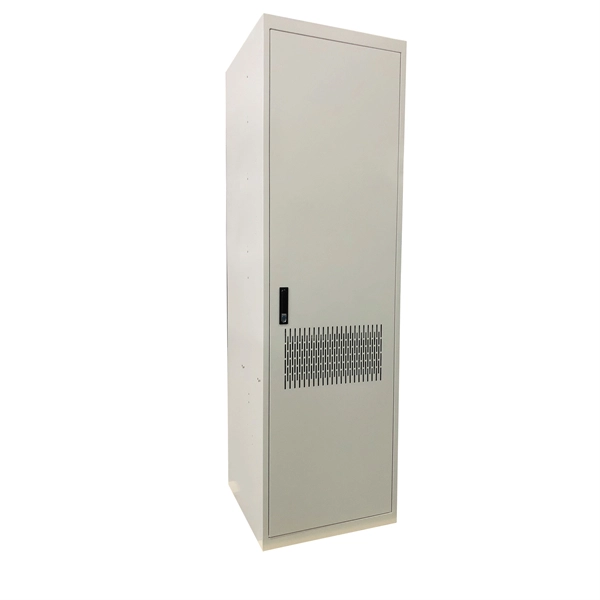
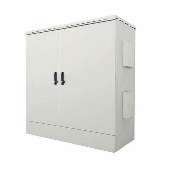
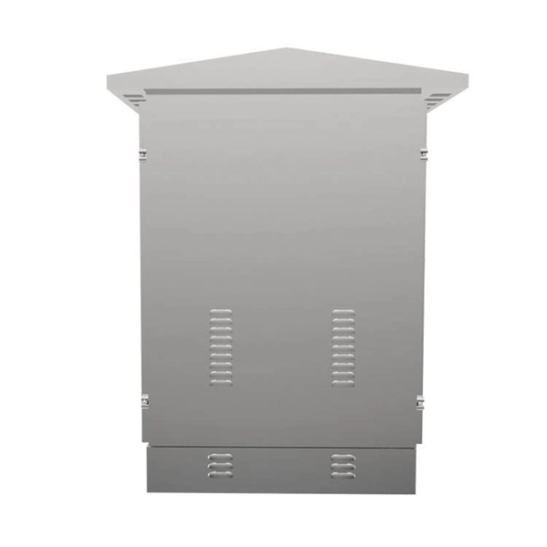
How to determine the installation method of a distribution box
Choose the right box based on environment (indoor/outdoor), load capacity, and durability. Check for proper IP/NEMA ratings and material quality. In this guide, we'll break down everything you need to know to install a distribution box correctly and confidently. Ensure safe placement: install in. Whether you are an electrical contractor or a construction brigade, knowing how to properly and safely install distribution boxes is the basis of ensuring the safe operation of the entire system. Just like travelers need clear pathways and safety protocols, your electrical circuits need proper management to prevent chaos. The National Electrical Code (NEC) requirements might seem like bureaucratic. How to determine the size, installation method and wiring mode of distribution box? (1) Wiring method of distribution box 1) Generally, the incoming line of power distribution box adopts five wire system, that is, a, B and C three-way phase line (the general color is yellow, green and red), one way. This methodology document highlights the technical guidelines for the installation of Electrical Distribution Boards (DBs). Respective electrical rooms, LV.
[PDF Version]
-
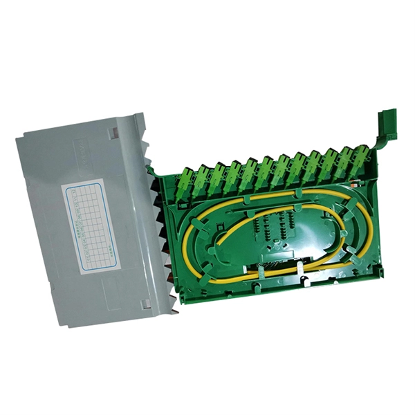
How much attenuation does a 1 8 beam splitter suffer
In PON equipment, the maximum attenuation value of OLT is between 22-25dB, which means that the attenuation value cannot exceed 25 dB. 1:2 PLC splitter attenuation is 3. 04 dB 1:32 PLC splitter. If we operate with absolute gains measured in relation to 1 milliwatt (mW), they are expressed in dBm, and are calculated as follows: Power Level (dBm) = 10 lg ( mW / 1 ) For “household” needs, in order not to calculate mW to dBm and vice versa every time, here's a ready-made correspondence table:. If you use a 1×8 splitter with ~10. 5 dBm This means each output port now only carries about 0. 089 mW (less than a tenth of the original power). This is crucial because: Optical receivers (like ONTs) need a certain. For instance, a 1:8 splitter ratio signifies an equal distribution of incoming optical power among eight output ports, with each port receiving 1/8th of the total power.
[PDF Version]
-
How to cut materials for cable tray tees
The bends, tees, crosses, risers and reducers of wire mesh cable tray can be easily and quickly made live at the project by using a bolt cutter. Since the jaws of the bolt cutter drags a layer of zinc across the cut end and forms a protective layer. When a wire cable tray is cut, the fact that a. Cable trays are essential components in electrical installations, providing a safe and organized pathway for cables and wiring systems. more Developed by Interstates, this cable tray cutting guide acts as a guide. In the Oglaend System Cutting Guideline you can easily find out what the optimal cutting lengths/intervals are for all modular products. Following the advice given. This manual is designed to guide workers through the detailed production process of ladder cable trays, including the manufacture of horizontal elbows, tees, crosses, reducing bends, and vertical bends, with emphasis on precision, safety, and quality control. What's Involved in Producing Ladder.
[PDF Version]
-
How to remove a loose pull ring from an optical module
Gently pull the module latch or release ring, depending on the module design. To use an SFP optical module, first confirm that the host port is SFP-type. Figure 1 SFP Optical Module Installation. However, with the right approach and careful handling, you can safely remove a transceiver stuck in a switch without causing damage to your network equipment. There are two primary reasons why an SFP module might become stuck in a port: The SFP is wedged in the cage: This can occur due to slight. To connect an optical cable to an SFP module, use the appropriate patch cord (e. Once connected, verify that the port activity indicator is on and run diagnostic commands to check the module status. After removing the fiber jumper, insert a clean dust cover over it to protect the end face of the module.
-
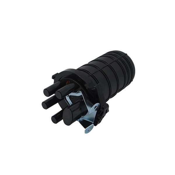
How to cut optical cables after production
Cutting fiber optic cable requires precision and the right tools to avoid damaging the delicate glass fibers that transmit data; the correct method involves scoring the outer jacket and then snapping the cable clean, ensuring a clean break for future splicing or termination. In this video, you will learn how to cut optical fiber cable step by step. This tutorial is perfect for beginners and professionals working with fiber optic cable installation and maintenance. You may also want to. 1. 1 Improper use of a respooler (Figure 1) can cause damage to a cable jacket or result in wavy fiber in tight buffered cables due to cable crossovers or excessive tensile loading. These cables are made of extremely The content is structured to help readers understand the key concepts and practical applications.
-
How far above the ground should fiber optic cables be
The International Telecommunication Union (ITU) and Institute of Electrical and Electronics Engineers (IEEE) recommend a minimum depth of 0. 6 meters for urban areas and 1. 0 meters for rural or agricultural zones to protect against frost, plows, and erosion. In urbanized areas, the cables usually need to be buried 30 to 60 cm below the surface. However, simply hitting this depth isn't enough to guarantee your network survives. Factors like the. Direct burial fiber optic cable must be specifically rated for this purpose, featuring a robust, often armored jacket to resist moisture, crushing, and rodent damage. Aerial installation is generally much less costly than underground construction also. Fiber in a duct solutions have a major aesthetic.
-
How to connect a contactor to a distribution box
First, find all the terminals on the contactor. Connect the line and load wires to the right terminals. Make sure. A contactor is an electromechanical switch that allows or interrupts the flow of electric current. It is widely used in applications such as motor control, lighting control, and power distribution. A contactor wiring diagram is a graphical representation of how contactors and other electrical. Properly wiring a contactor means connecting the control circuit to the coil terminals (A1/A2) and the high-voltage power circuit to the line (L1/L2/L3) and load (T1/T2/T3) terminals.
-
How to ground the busbar of the switchgear
Bus bar grounding can be achieved by one of two methods: grounding clamps applied to bus bars or a separate switchgear section with a switching mechanism dedicated to ground. In most assemblies you will find horizontal main bars, vertical risers, neutral and equipment-ground buses, and purpose-designed. The purpose of this manual is to assist the user in developing safe and eficient procedures for the installation, maintenance and operation of the equipment. For additional information, refer to NEMA Standards Publication PB2. Dive in to power up your knowledge! These guidelines govern the busbar processing and installation procedures. With the exception of SF6-to-air bushings terminals, all active portions of gas-insulated switchgear (GIS) are contained within grounded enclosures, which means that they are not susceptible to inadvertent contact. This makes gas-insulated switchgear intrinsically safe. In addition, numerous. New Approaches for Maintenance Grounding in Medium-Voltage Switchgear by Joe Richard and David Mabius Executive summary Maintenance grounding has traditionally been performed by maintenance personnel working in close proximity to open switchgear.
[PDF Version]
-
How to connect cable trays to the ground
If cable trays are to be used as grounding points, their connection points must be grounded using flexible jumpers with lugs of appropriate cross-sections. An EGC conductor in or on the cable tray. There are three wiring. Cable tray systems have become an essential component in the infrastructure of modern commercial buildings, smart offices, data centers, and various industrial facilities. These systems provide an efficient and adaptable solution for managing a wide range of cables, including power cables, control. When setting up electrical systems, grounding is a must. The Cable Tray Grounding Wire ensures everything runs safely and smoothly. In accordance with National Electrical Code (NEC) Article 392 “Cable trays” first determine the Maximum Fuse Ampere Rating or Circuit Breaker Ampere Trip Setting or Circuit Breaker Protective Relay Ampere Trip Setting for Ground-Fault Protection s the minimum.
[PDF Version]