-
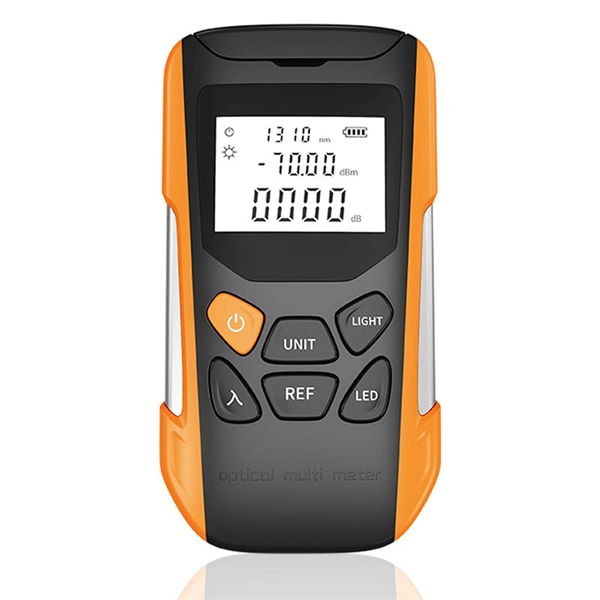
How to measure the light received and emitted by the light module
Lumen (lm): Measures the total visible light emitted by a source. Candela (cd): Focuses on the intensity of light in a specific direction, measured as lumens . From the measurement of light in the electromagnetic spectrum, to understanding perceived brightness to the human eye, light intensity and the tools used to measure light, this guide covers it all. Radiometry is important when physical metrics must be preserved, such as in simulation tasks, and photometry is important in subjective. We speak of light energy as 'flux' and luminous flux is a measure of the flow of light energy emitted by a source, or received by a surface. Measure a known good sample and compare the measurements to your test samples.
-
How to measure wear using fiber optic sensors
When the wafer dicing saw processes hard and brittle materials, the wear rate of the grinding wheel blade accelerates. To detect blade wear in time, a grinding wheel blade wear detection method based on a f.
-

How to measure the optical attenuation value of fiber optic patch cords
The primary tool for measuring attenuation in installed fiber is an Optical Time Domain Reflectometer, or OTDR. The most fundamental parameter for optical fiber is geometry, since the dimensions of the fiber determine its ability to be spliced and terminated to other fibers. The core diameter, cladding diameter and concentricity are the most important factors on how well one can connect or splice two fibers. In this tutorial, we'll take a look at the.
-
How much light output is normal from a secondary beam splitter
A beam splitter or beamsplitter is an optical device that splits a beam of light into a transmitted and a reflected beam. It is a crucial part of many optical experimental and measurement systems, such as interferometers, also finding widespread application in fibre optic telecommunications. DesignsIn its most common form, a cube, a beam splitter is made from two triangular glass which are glued together at their base using polyester,, or urethane-based adhesives. (Before these synthetic,. Beam splitters are sometimes used to recombine beams of light, as in a. In this case there are two incoming beams, and potentially two outgoing beams. But the amplitudes. For beam splitters with two incoming beams, using a classical, lossless beam splitter with Ea and Eb each incident at one of the inputs, the two output fields Ec and Ed are linearly related to the inputs thro.
[PDF Version]
-
How a monochromator separates light
By using dispersive elements like prisms or diffraction gratings, a monochromator separates light into its component wavelengths and selectively transmits the desired one. The device converts polychromatic light into a nearly monochromatic beam, meaning a single, specific color of light. In food quality testing, this ability to isolate specific wavelengths is what enables scientists. monochromator, instrument that supplies light of one colour or light within a narrow range of wavelengths. The monochromator is used to photograph the Sun and.
-
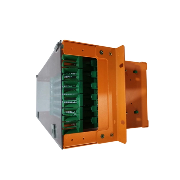
How to measure the loss rate of a beam splitter
To accurately measure optical splitter loss, utilize optical test equipment like power meters and spectral analyzers. Here's how: Measure the optical power at both the input and output ports of the splitter. This loss is primarily quantified as insertion loss, which measures the reduction in signal power due to the splitter's presence in the optical path. Common values: 2, 4, 8, 16, 32, 64.
-
How to measure the protection action time of relay protection instruments
We provide guidance regarding test signals, propose a number of ways to measure and compare relay performance, discuss the issue of type testing, and review requirements for transient simulation and playback tools for testing ultra-high-speed line protective relays. Action time, as an important indicator to measure the response speed of relay protection devices, reflects the duration from the input of fault signals to the output of actions of the protection devices. The setup serves to simulate faults and create transient waveforms. Abnormalities are detected of the protection relay with the help of the following general tests: This basic test determines the time that the relay takes to respond when detecting these faults. Then, set the tester parameters, including the operating voltage, operating current, and the phase angle between voltage and current. We review traditional performance measures, such as transient overreach for distance zone 1, and formalize other measures, such as operating time and dependability. Ensure protection systems operate correctly.
[PDF Version]