-
How to bridge a wireless network
Wi-Fi wireless bridging is the process of connecting two or more wireless networks together to form one larger network. It involves using wireless routers or access points to create a bridge between two different Wi-Fi networks, allowing devices to move seamlessly between them. A wireless bridge connects two routers over Wi-Fi, letting devices share one internet connection without long Ethernet cables. Bridging an internet connection refers to making connections between different ports that will be used by your computer, such as ethernet and wireless. In this. This is where creating a Wi-Fi bridge comes in handy.
-
How to prevent fiber optic routers from being damaged
Identifying and resolving issues in fiber optic systems helps maintain peak performance and reliability. Regular inspection, maintenance, and adherence to standards and best practices can minimize fiber optic problems. Key Risks and How to Fiber-optic cables are the backbone of modern connectivity—powering 5G networks, global internet backbones, and data center interconnections with near-light-speed data transmission. While these cables are engineered for durability (with some rated to last 25+ years), they are. Fiber optic cabling is one of the most reliable and high-performing ways to transfer data over long distances. Repairs focus on restoring the light path with minimal signal loss (<0.
-
How far is the long-span bridge between China and Africa
66 kilometers with a four-lane dual carriageway and a design speed of 120 km/h, the Magufuli Bridge features a 520-meter, three-tower extradosed main span built using the balanced cantilever method. Magufuli Bridge—the longest extradosed cable-stayed bridge in Africa—was officially opened to traffic in Tanzania. Constructed by China Civil Engineering Construction Corporation (CCECC) and China Railway 15th Bureau Group, the project was inaugurated by Tanzanian President. BEIJING, June 26, 2025 (GLOBE NEWSWIRE) -- The JP Magufuli Bridge in Tanzania's Mwanza Province officially opened to traffic on June 19, 2025. Built by China Railway Construction Corporation Limited (CRCC), the 4. 9 mi) in length sorted by their full length above land and water.
-
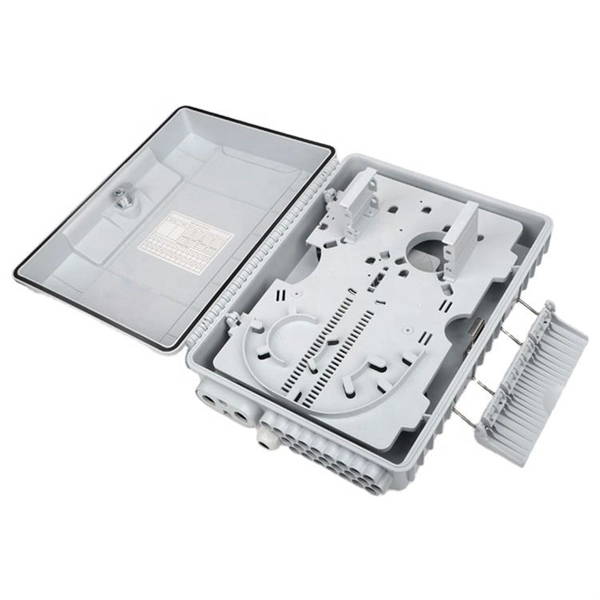
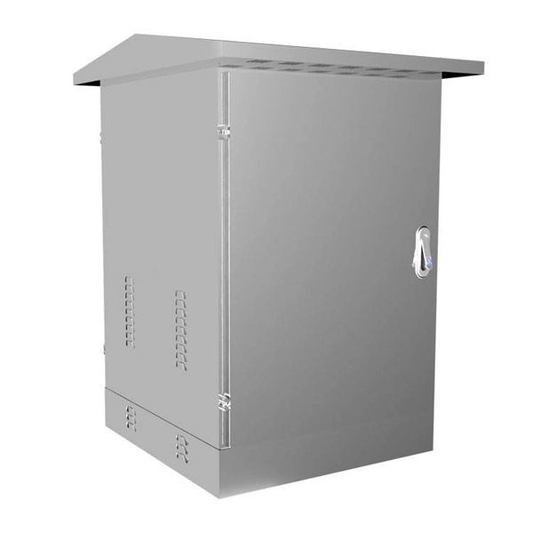
How to disconnect the power when installing a distribution box
To handle this safely, technicians must follow a strict lockout-tagout (LOTO) procedure. This ensures that no accidental reconnection occurs while the wires are being adjusted or inspected within the housing. Identify all power sources feeding the specific distribution blocks. The service disconnect rules, primarily outlined in NEC Article 230, Part VI, are fundamental to electrical safety, providing the means to de-energize an entire building from its power source. For a journeyman electrician or master electrician, a deep understanding of these regulations is. Before installation, it's important to know what makes up a distribution box. It has three categories: residential, commercial and industrial electrical distribution boxes, all of which play important roles in their respective electrical. Always shut off the power to an outlet before working on it—and then test with an electrical tester to be sure there's no voltage present. It is usually equipped with circuit breakers, fuses, terminal connectors, and other components.
[PDF Version]
-

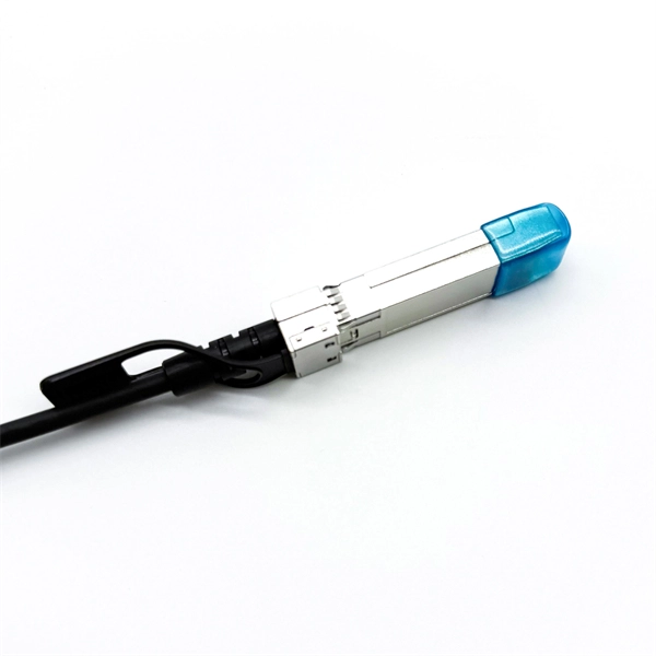
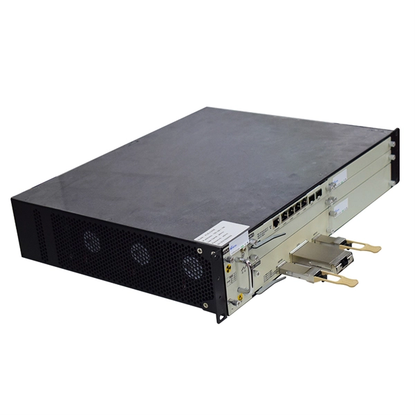
How to connect the 10 Gigabit Ethernet cable to the fiber-to-electrical port module
A special 10G Copper RJ-45 Transceiver (10G-SFP-T) is required to connect the SFP+ port to RJ45. It allows connecting a server/storage side Cat6/7 cable to an SFP+ port transceiver. An SFP module (or optical transceiver) converts electrical signals from network devices (switches, routers) into optical signals for fiber transmission and vice versa. 1G/10G SFP+: Standard for Gigabit and 10 Gigabit Ethernet. These transceiver modules are hot-swappable input/output (I/O) devices that plug into 100BASE, 1000BASE and 10GBASE ports (for SFP+), which connect the module port with the fiber-optic or copper network. 4ft (30m) * using Cat6a/Cat7 or above cable for 10G connection in various applications. In this video, we'll guide you through building a high-speed 10G LAN by connecting two fiber switches. Finally, check the transmit (TX) and receive (RX) paths to ensure that signals are aligned.
[PDF Version]
-
How is the serial interface of the XFP optical module
The XFP 2-wire serial interface is used for serial ID, digital diagnostics, and certain control functions. It was defined by an industry group in 2002, along with its interface to other electrical components, which is called XFI. XFP modules can be installed or replaced in an Extreme Networks switch, I/O module, or router without powering off the system. All Extreme Networks XFP modules comply with. This Juniper Networks® XFP-10G-S compatible XFP transceiver provides 10GBase-SR throughput up to 300m over multi-mode fiber (MMF) using a wavelength of 850nm via an LC connector. It can operate at temperatures between 0 and 70C. The transceiver is compliant with CPRI, eCPRI. With these features, this 10G SFP+. ID systems defined for the GBIC and SFP transceivers. 12 document apply to Beta-and Production-level units only. Physical Medium Dependent (PMD) sublayer and baseband medium, type 10GBASE-S (short wavelength serial), 10GBASE-L (long wavelength serial), and.
[PDF Version]
-
How to Select a Beam Splitter Circuit
This is vital in diverse fields from scientific research to consumer electronics. They operate with coherent or incoherent light, splitting by intensity, wavelength, or polarization. Plate beamsplitters are. Beamsplitters are used in laser systems, optical interferometry, fluorescence, and biomedical instrumentation. This division allows for the simultaneous analysis or utilization of the light's properties along two separate paths. See the Comprehensive Guide for worked examples, SVG diagrams, and full references.
-
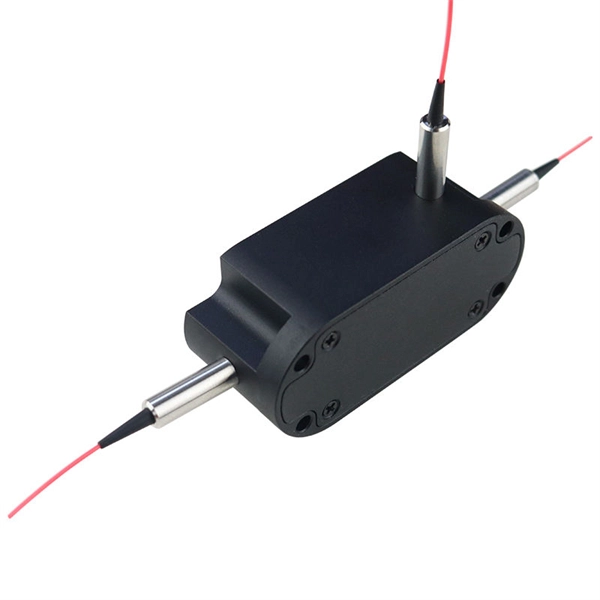
How to connect optical cables to split them into multiple paths
Optical couplers can split or join signals in fibers. These devices work both ways, which helps strong network communication. For example, optical splitters send light to many output ports. You can also use them to join light from. Before attempting to split a fiber optic cable, gather the necessary tools and equipment: Fiber Optic Splitter: This device divides a single optical signal into multiple signals. It typically consists of an MPO connector on one end, which can accommodate multiple fibers, and multiple connectors (such as LC or SC) on the other end, each. Optical splitters offer a cost-effective and dependable solution across various fiber optic applications. Also known as optical splitters, fiber splitters, or beam splitters, these devices are integrated waveguides ensuring wide bandwidth and minimal loss in high-frequency applications. This device takes the incoming light signal and divides it into multiple paths, allowing the signal to be sent to multiple devices.
[PDF Version]
-
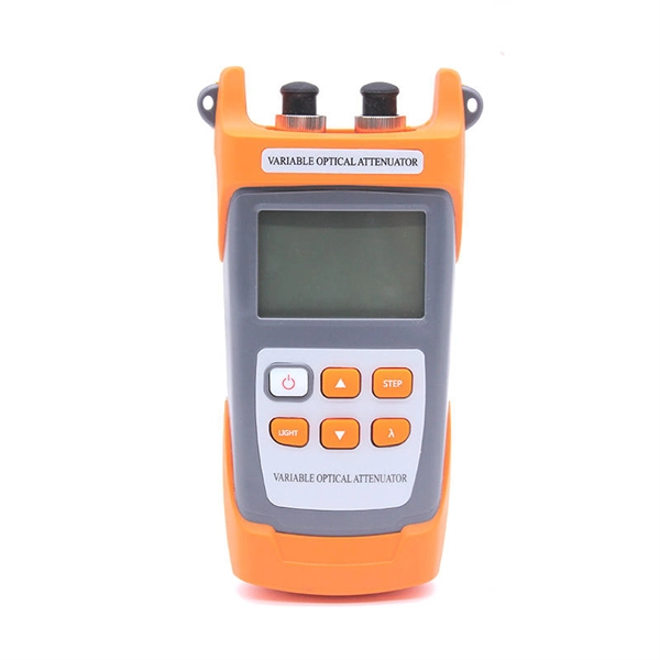
How to determine light attenuation of red light using an optical power meter
Optical attenuation compares input and output power on a logarithmic scale. When powers are in linear units, the loss in decibels is: Attenuation (dB) = 10 × log10 (Pin / Pout) If the link length L is provided, the attenuation coefficient is: Coefficient (dB/km) =. Analyze optical power drop across fibers and links. Switch units, lengths, and calculation modes easily. Needed when attenuation is an. Optical power, required for measuring source power, receiver power and, when used with a test source, loss or attenuation, is the most important parameter and is required for almost every fiber optic test. Backscatter and wavelength measurements are the next most important and bandwidth or. Optical power meters are a key element in the optimization and maintenance of such optical networks and of their components. But, for designers, just starting to work in the fiber-optic design space, measuring attenuation can seem like a monumental task.
[PDF Version]
-
How to connect cable trays to the ground
If cable trays are to be used as grounding points, their connection points must be grounded using flexible jumpers with lugs of appropriate cross-sections. An EGC conductor in or on the cable tray. There are three wiring. Cable tray systems have become an essential component in the infrastructure of modern commercial buildings, smart offices, data centers, and various industrial facilities. These systems provide an efficient and adaptable solution for managing a wide range of cables, including power cables, control. When setting up electrical systems, grounding is a must. The Cable Tray Grounding Wire ensures everything runs safely and smoothly. In accordance with National Electrical Code (NEC) Article 392 “Cable trays” first determine the Maximum Fuse Ampere Rating or Circuit Breaker Ampere Trip Setting or Circuit Breaker Protective Relay Ampere Trip Setting for Ground-Fault Protection s the minimum.
[PDF Version]
-
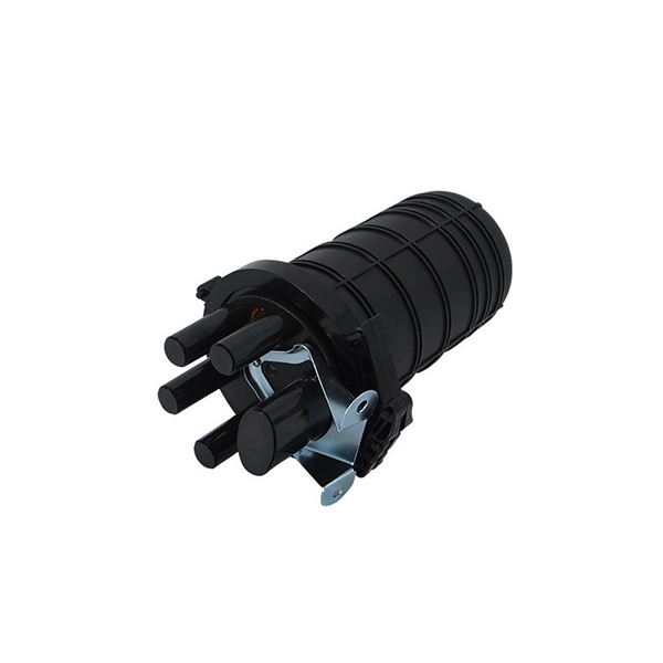
How to locate the fault point in a communication optical cable
Struggling to identify faults, validate polarity or ensure quality mechanical connector terminations in your fiber optic cables? Visual Fault Locators (VFLs) are a valuable tool that make troubleshooting fast and efficient. Let's dive into everything you need to know about mastering VFLs. Common Indicators of a Cable Break Signal Loss or Interruption: If data transmission is interrupted, it could indicate a break or severe bend. Physical. Finding a fiber fault typically involves the following steps: 1. However, physical damage can disrupt this infrastructure and cause significant network issues. When fiber cables sustain damage, specialized repair techniques help. To ensure the quality and continuity of fiber optic services, it is essential to identify and locate fiber optic cable faults as quickly and accurately as possible.
-
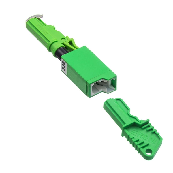
How to connect a fiber optic cold connector 6
This blog provides a step-by-step guide on how to connect fiber optic cable to connector using a fast cold connector. It explains the installation process, key features, benefits, and common issues. In this article, we will. ⚡ Level Up Your Fiber Skills – Join the One Up Techs Skool 👉 https://www. Please like, Subscribe, and comment any questions you may have. This comprehensive guide covers SC/APC vs SC/UPC fast connectors, selection criteria, installation best practices, compatibility considerations, and application-specific. Proper connection of fiber optic cables is essential to harness these benefits fully, as even minor errors can lead to significant performance issues like signal loss.