-
How to bridge a wireless network
Wi-Fi wireless bridging is the process of connecting two or more wireless networks together to form one larger network. It involves using wireless routers or access points to create a bridge between two different Wi-Fi networks, allowing devices to move seamlessly between them. A wireless bridge connects two routers over Wi-Fi, letting devices share one internet connection without long Ethernet cables. Bridging an internet connection refers to making connections between different ports that will be used by your computer, such as ethernet and wireless. In this. This is where creating a Wi-Fi bridge comes in handy.
-

A Comprehensive Guide to Seismic Supports for Palestinian Bridge Structures
Hatem Alwahsh f• Dynamic analysis: the analysis shall be based on an appropriate ground motion representation and shall be performed using accepted principles of dynamics. The main methods of dyn.
-
How far is the long-span bridge between China and Africa
66 kilometers with a four-lane dual carriageway and a design speed of 120 km/h, the Magufuli Bridge features a 520-meter, three-tower extradosed main span built using the balanced cantilever method. Magufuli Bridge—the longest extradosed cable-stayed bridge in Africa—was officially opened to traffic in Tanzania. Constructed by China Civil Engineering Construction Corporation (CCECC) and China Railway 15th Bureau Group, the project was inaugurated by Tanzanian President. BEIJING, June 26, 2025 (GLOBE NEWSWIRE) -- The JP Magufuli Bridge in Tanzania's Mwanza Province officially opened to traffic on June 19, 2025. Built by China Railway Construction Corporation Limited (CRCC), the 4. 9 mi) in length sorted by their full length above land and water.
-
How to install the cable tray beam bend
The fittings can fastened to the cable tray rail either with double clamps of type DOP A2 or with truss-head bolts of type FRS and combination nuts. The exceptions to this are vertical bends, adjustable bend elements and fittings with a side height of 35 mm. These fittings can only be screwed on. Beam bracket PK1 is attached to the lower flange of an I beam. These guidelines are not intended to cover all details or variations in cable ladder and cable tray. en completely installed, without damage either to conductors or structural system use maintain spacing or to keep cables in place when the tray is ect the minimum bend ra-dius for cables as they exit the bottom of the cable tray. A rung spacing of 6 to 9 inches (150 to 230 mm) is preferable when. Hubbell's NEXTFRAME® Ladder Tray is the effective and widely used cable runway that supports and delivers bundles of cable between cabinets, racks, and closets, along walls, and suspended from ceilings. Cable ladder systems and cable tray systems shall be manufactured in accordance with BS EN 61537, channel support.
[PDF Version]
-
How to connect cable trays to the ground
If cable trays are to be used as grounding points, their connection points must be grounded using flexible jumpers with lugs of appropriate cross-sections. An EGC conductor in or on the cable tray. There are three wiring. Cable tray systems have become an essential component in the infrastructure of modern commercial buildings, smart offices, data centers, and various industrial facilities. These systems provide an efficient and adaptable solution for managing a wide range of cables, including power cables, control. When setting up electrical systems, grounding is a must. The Cable Tray Grounding Wire ensures everything runs safely and smoothly. In accordance with National Electrical Code (NEC) Article 392 “Cable trays” first determine the Maximum Fuse Ampere Rating or Circuit Breaker Ampere Trip Setting or Circuit Breaker Protective Relay Ampere Trip Setting for Ground-Fault Protection s the minimum.
[PDF Version]
-
How to locate the fault point in a communication optical cable
Struggling to identify faults, validate polarity or ensure quality mechanical connector terminations in your fiber optic cables? Visual Fault Locators (VFLs) are a valuable tool that make troubleshooting fast and efficient. Let's dive into everything you need to know about mastering VFLs. Common Indicators of a Cable Break Signal Loss or Interruption: If data transmission is interrupted, it could indicate a break or severe bend. Physical. Finding a fiber fault typically involves the following steps: 1. However, physical damage can disrupt this infrastructure and cause significant network issues. When fiber cables sustain damage, specialized repair techniques help. To ensure the quality and continuity of fiber optic services, it is essential to identify and locate fiber optic cable faults as quickly and accurately as possible.
-
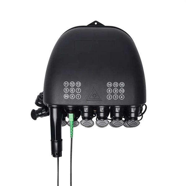
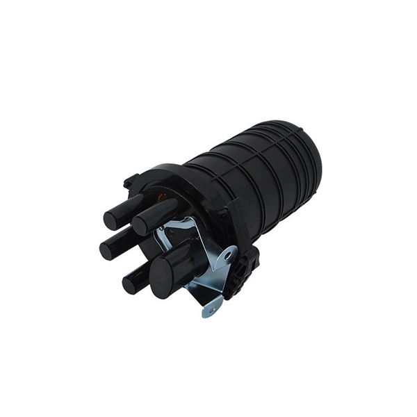
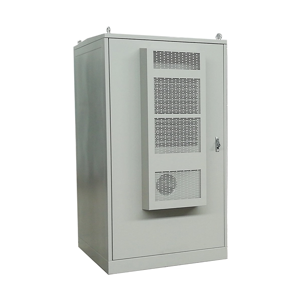
How to waterproof the connecting pipe of the optical distribution box
The cap-type splice box uses a heat-shrinkable sleeve to seal the lead-in part of the optical cable into the splice box, and connects the line optical cable and the splice box as a whole. The upper and lower covers squeeze the rubber ring to make it waterproof. Extended size. Waterproofing an electrical connection is all about creating a bulletproof barrier against moisture.
-
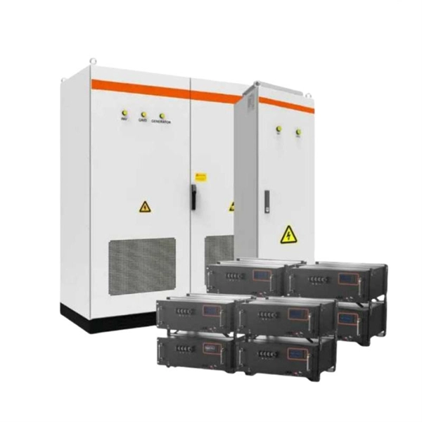
How to Choose a Swiss Explosion-Proof Distribution Box
Explosion Proof Distribution Box & Electrical Enclosures are certified for Class I, Division 1 and Class II, Division 1. You need to check if the enclosure fits the danger level and protection type. For example, you might need Ex d for flameproof or Ex i for safe designs. In this article, we will explore three key aspects:. ·Flameproof enclosure (Ex db), which can be used as feed distribution equipment in control and distribution system (such as distribution box, switch box of main circuit, control box, terminal box or motor starting box etc. They prevent sparks, arcs, or high temperatures generated by internal electrical components from coming into contact with explosive gases or dust in the surrounding atmosphere. With a wide range of enclosure materials, sizes, ambient temperature ranges, and customizable configuration s, these solutions can. Options range from Ex d (flameproof enclosure) to Ex e (increased safety) and Ex i (intrinsically safe) right through to Ex p (pressurized housing), as well as combinations of different explosion-protection types – always bearing in mind the most efficient solution for your application.
[PDF Version]
-
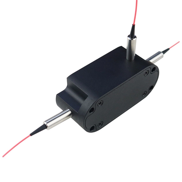
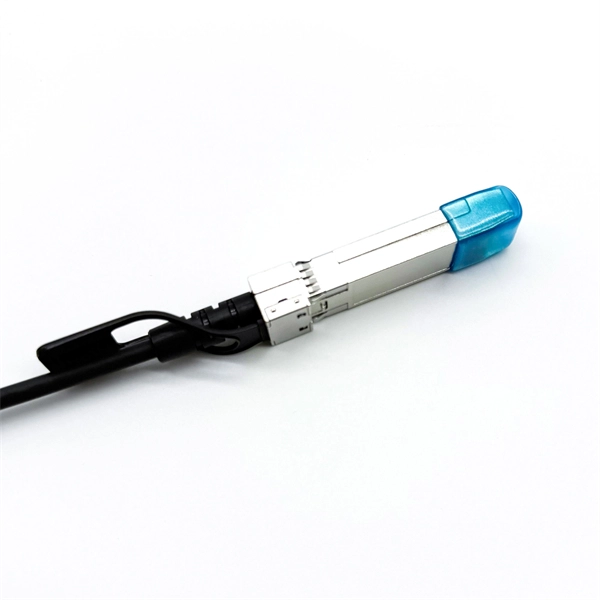
How to connect optical cables to split them into multiple paths
Optical couplers can split or join signals in fibers. These devices work both ways, which helps strong network communication. For example, optical splitters send light to many output ports. You can also use them to join light from. Before attempting to split a fiber optic cable, gather the necessary tools and equipment: Fiber Optic Splitter: This device divides a single optical signal into multiple signals. It typically consists of an MPO connector on one end, which can accommodate multiple fibers, and multiple connectors (such as LC or SC) on the other end, each. Optical splitters offer a cost-effective and dependable solution across various fiber optic applications. Also known as optical splitters, fiber splitters, or beam splitters, these devices are integrated waveguides ensuring wide bandwidth and minimal loss in high-frequency applications. This device takes the incoming light signal and divides it into multiple paths, allowing the signal to be sent to multiple devices.
[PDF Version]
-
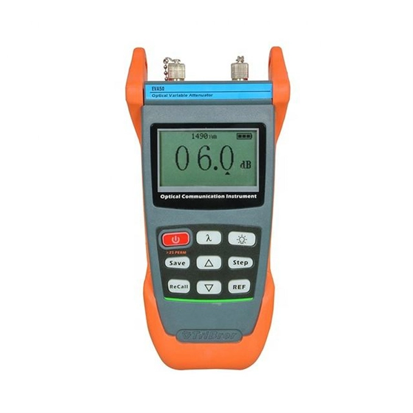
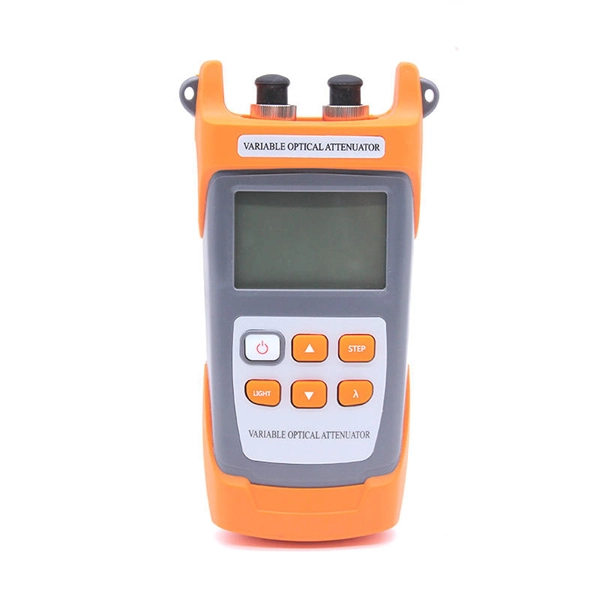
How to measure the loss rate of a beam splitter
To accurately measure optical splitter loss, utilize optical test equipment like power meters and spectral analyzers. Here's how: Measure the optical power at both the input and output ports of the splitter. This loss is primarily quantified as insertion loss, which measures the reduction in signal power due to the splitter's presence in the optical path. Common values: 2, 4, 8, 16, 32, 64.