-
How to Choose a Tunable Optical Module SFP 2026
A practical, engineer-friendly guide to choosing the right transceiver form factor by speed, port density, power, migration plan, and operational risk—built for 25G/100G networks in 2026. 25G SFP28 is the new access/server baseline; deploy it for port density and long-term value. 100G QSFP28 is the. Published: 2026 | Category: Network Hardware Knowledge Base / Optical Communications Core Keywords: SFP Module, SFP Transceiver, Small Form Factor Pluggable, What is SFP, SFP vs SFP+ Read Time: Approx. 25 Minutes Even in the era of Wi-Fi 7 and 5G, Optical Transceivers remain the backbone of the. By the Network-Switch. SFP/SFP+: The standard for 1G/10G campus and. SFP-family and QSFP-family transceivers are hot-pluggable modules that convert electrical signals to optical signals (and back) for fiber links in switches, routers, servers, and transport platforms.
[PDF Version]
-
How to read the wavelength of a source optical module
In fiber optic networks, accurately identifying the wavelength of an optical transceiver module is essential for ensuring optimal network performance and reliability. One of the most effective and widely used methods is through the pull-tab color on transceiver modules. This simple visual system. That's where an Optical Spectrum Analyzer (OSA) comes in—a powerful instrument that measures the wavelength, power, and spectral characteristics of light. Think of it as a "microscope for light," revealing details invisible to the naked eye. We all know that CWDM has a total of 12 wavelengths, with a full band range of 1270-1610nm, with each wavelength interval of 20nm. SFP+: small form-factor pluggable plus, SFP with a higher rate. Considering that some newcomers to optical modules may not understand the letters on the optical module or the. Optical power, required for measuring source power, receiver power and, when used with a test source, loss or attenuation, is the most important parameter and is required for almost every fiber optic test.
[PDF Version]
-
How to remove the 10G optical module
To safely remove an SFP module, follow these steps: Disable the port in your network device settings or power off the device to avoid electrical damage. Gently pull the module latch or release ring, depending on the module design. To prevent damage to a transceiver and to any connected cables, disconnect all cables before installing or removing a module. There is no need to. Before installing an SFP or SFP+ module, we need to know some caution tips first.
-
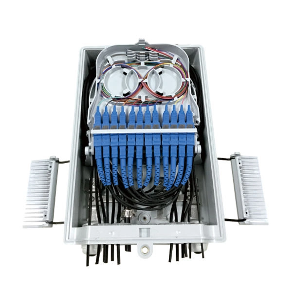
How to connect a network module to a patch panel
Learn the step-by-step network patch panel and keystone jack wiring methods, including essential tools, T568A/B wiring sequences, and tool-free installation tips. Attach the cable manager to the patch panel port. Note the wiring sequence on the patch panel when wiring, as T568A and T568B. When you're building a network, it's often ideal to use a patch panel to direct cables and organize long Ethernet runs — especially if they go through walls, floors, and/or ceilings. Patch panels make cable management and network organization very easy over long periods of time, but you'll need to. Patch panel and switch are commonly used to connect devices in data centers and telecom rooms, and they are usually mounted on a server rack. Patch panels aren't so difficult to understand but might be a little intimidating at first if you're new to structured wiring. Following these steps helps you build a clean and efficient structured cabling system that simplifies maintenance and maximizes network performance. Before a single cable is.
[PDF Version]
-
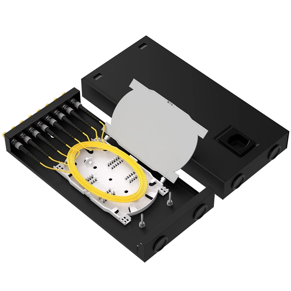
How to check optical loss on a Huijue switch
Execute the command, display transceiver [ interface interface-type interface-number | slot-id ] [ verbose ] to check the optical module information on the device interface. During use, reading optical module information helps understand its real-time operating status, enabling faster troubleshooting of link abnormalities. The following uses the. Here is an example on how to query or display optical power of an interface in a Huawei Router. from transceivers Check “Alarm information” section for warnings, LOS Alarm means no inbound signal, execute display this to check shutdown mode, execute undo shutdown if necessary. Execute the command, display.
-
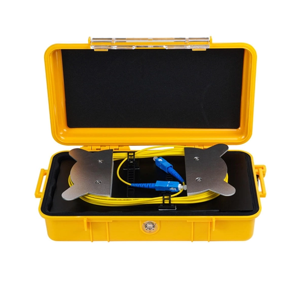
How to check the router s fiber optic cable
To check a fiber connection, connect a jumper to the optical source port and the other end to an optical meter. Press the “test” or “signal” button to send a signal from the source to the meter. When your fiber optic network stops working, begin with a structured approach. Many fiber internet problems come from dirty connectors or loose plugs, not major faults. This test requires a special testing kit and protective eyewear, but it will help you diagnose problems with the cable's. Whether you're a professional or a DIY enthusiast, knowing how to test fiber optic cables is crucial. In this blog, we'll explore different methods, including using a flashlight, advanced tools like Fluke testers, and more cost-effective options for testing fiber optics. First, we'll show you the. To connect your fiber optic cable to a router, ensure you have the following: Fiber optic modem (ONT): Most fiber connections require an Optical Network Terminal (ONT), provided by your ISP.
[PDF Version]
-
How to insert the Huijue optical module
Connect the XFP transceiver module to the network using an optical cable. After the optical cable is plugged into the transceiver, the LINK/ACT LED on the switch turns on. The following types of form. This section describes how to install an optical module. It is also prohibited to translate the document into other languages or use any or all parts of. P module is an input/output device that supports hot swapping.
-
Ciscoh3C optical module compatibility
Link to compatibility matrix tool: Click here. com The current compatibility matrix allows users, typically Cisco customers and sales, to determine what transceivers are supported in Cisco hardware devices such as switches/routers and line cards/modules. Cisco does not support third party optics. For the guideline on third party components, see Section 6 of Cisco's Non-Entitlement Policy. For ONS Family optics product and compatibility information, please click here For High-Density Fiber Patch Panel, Simplex, MPO and Breakout Cables Portfolio Data. Optical modules transmit signals over optical fibers. Optical transmission features low loss and is fit for long distance transmission. The information is displayed in a. The following table shows the available transceiver modules for interface modules, MPUs, subcards, and devices.
[PDF Version]
-
How are the pins of the 2609B optical receiver module
With 900um-buffered single-mode fiber, without fiber connector. Internal current gain: 6 dB (typ. The 2609B is a packaged impedance-matched photodiode module with internal gain designed for use in optical broadband receivers in. The 2609B is a packaged impedance-matched photodiode module with internal gain designed for use in optical broadband receivers in fiber-optic networks. These are absolute stress ratings only. Functional operation of the device is not implied at these or any other conditions in excess of those given in the operational sections of the data sheet. Exposure to. no available.
-
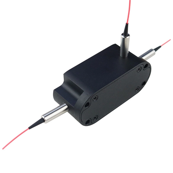
Does the optical splitter need an optical module and how is it connected
The optical transceiver module (like an SFP, SFP+, or XFP module) in the OLT is the laser source that generates the initial light signal. This high-power signal is transmitted down the single fiber. When it reaches the optical splitter, the signal is divided and sent. A fiber optic splitter is a passive optical component that divides a single incoming optical signal into two or more outgoing signals, or combines multiple incoming signals into one. Conversely, it can also combine multiple signals into one. It is a passive optical device with many input and output terminals, especially applicable to. An Optical Splitter (also known as a fiber optic splitter or beam splitter) is a passive optical power management device.
-
How to measure the light received and emitted by the light module
Lumen (lm): Measures the total visible light emitted by a source. Candela (cd): Focuses on the intensity of light in a specific direction, measured as lumens . From the measurement of light in the electromagnetic spectrum, to understanding perceived brightness to the human eye, light intensity and the tools used to measure light, this guide covers it all. Radiometry is important when physical metrics must be preserved, such as in simulation tasks, and photometry is important in subjective. We speak of light energy as 'flux' and luminous flux is a measure of the flow of light energy emitted by a source, or received by a surface. Measure a known good sample and compare the measurements to your test samples.