-
How to select the power cord for the distribution box
Some distribution boxes have a longer cord than others. If it's too short, you may not be able to connect the distribution box. Covers wiring, placement, standards, and expert tips for a compliant setup. In modern electrical systems, cable distribution boxes (also known as electrical distribution boxes or distribution boxes) play a crucial role as the key hub for managing, distributing, and protecting circuits. Key Takeaways: Begin cable and conductor. With designations such as NM and UF, building cable brings power to wall outlets and outlet boxes Make connections in low-voltage vehicle wiring systems Connect servocontrollers and servomotors in automated equipment and on assembly lines With designations such as THHN or THWN, building wire brings. Hey, in this article we are going to see the Single Phase Distribution Box Wiring Diagram and Connection Procedure. And all the switching and protective devices are installed in the.
[PDF Version]
-
How to select circuits on the distribution box panel
Use electrical diagrams to see where circuits go. Make sure the breaker matches what it protects. This stops fires and helps everything work right. What size distribution box do you need for a house? How do you know which circuit breaker to use? Can you add more breakers later? Why do you need GFCI or AFCI breakers? Choosing the right size and setup for your distribution box keeps your electrical system safe and working well. You lower the. This guide provides information on how to select the appropriate Distribution Box for Electric project. Whether you're upgrading your home's electrical service, designing a commercial facility, or managing an industrial power system, selecting and sizing the right. The distribution box (DB box) plays a key role in safely and efficiently distributing electrical power.
-
Most unfavorable operating mode of relay protection
Protection relay misconfiguration refers to incorrect setup of relay parameters that causes the device to operate outside its intended protection logic. Unlike hardware failure, the relay remains functional, but its decision-making is wrong. However, in many real-world plants, failures are not caused by relay hardware itself but by incorrect configuration, outdated settings. This handbook covers the code of practice in protection circuitry including standard lead and device numbers, mode of connections at terminal strips, colour codes in multicore cables, dos and donts in execution. They are intended to quickly identify a fault and isolate it so the balance of the system continue to run under normal conditions.
-
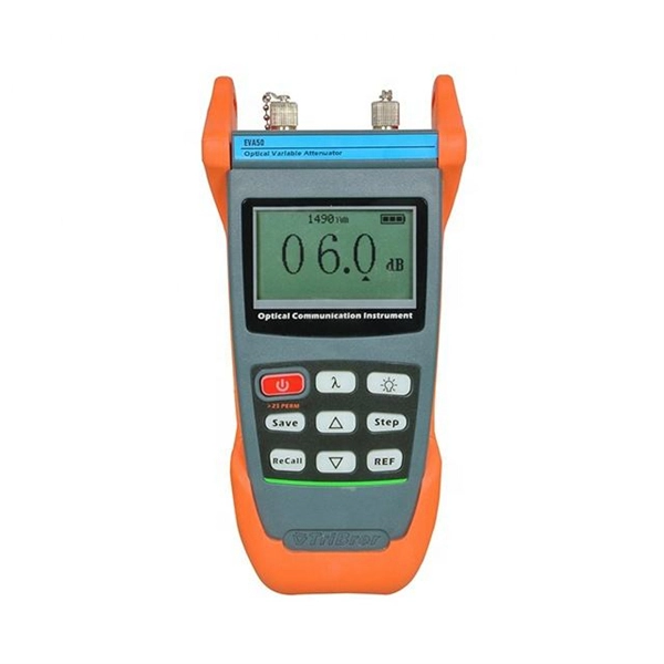
How are optical power meters classified
An optical power meter (OPM) is a device used to measure the power in an signal. The term usually refers to a device for testing average power in systems. Other general purpose light power measuring devices are usually called,, power meters (can be sensors or ), or lux meters. A typical optical power meter consists of a , measuring and display. The sens.
-
How to protect the wires in a three-level distribution box
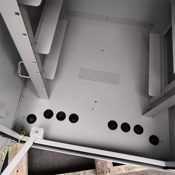
A neat, well-organized subpanel bundles wires to conserve space and improve access. The enclosure protects the electrical components from water, dust, and damage. The box is usually made of steel or plastic. They are one-pole modular units with an interlocking. Above finished grade or sidewalks, or from any platform or projection from which they might be reached. Label short sheathing sections (slugs) to indicate which circuits wires serve.
-
How to install the cable tray beam bend
The fittings can fastened to the cable tray rail either with double clamps of type DOP A2 or with truss-head bolts of type FRS and combination nuts. The exceptions to this are vertical bends, adjustable bend elements and fittings with a side height of 35 mm. These fittings can only be screwed on. Beam bracket PK1 is attached to the lower flange of an I beam. These guidelines are not intended to cover all details or variations in cable ladder and cable tray. en completely installed, without damage either to conductors or structural system use maintain spacing or to keep cables in place when the tray is ect the minimum bend ra-dius for cables as they exit the bottom of the cable tray. A rung spacing of 6 to 9 inches (150 to 230 mm) is preferable when. Hubbell's NEXTFRAME® Ladder Tray is the effective and widely used cable runway that supports and delivers bundles of cable between cabinets, racks, and closets, along walls, and suspended from ceilings. Cable ladder systems and cable tray systems shall be manufactured in accordance with BS EN 61537, channel support.
[PDF Version]
-
How to connect the fiber optic box and the terminal box
Secure the box with screws (ensure depth ≥40mm). Run incoming fiber cable through the box's entry port. Connect ONT to socket with. Learn how to install a fiber optic termination box step-by-step for FTTH projects. Covers mounting, splicing, routing, labeling, and testing for indoor/outdoor use. Thus, a fiber termination box is used to terminate the optical fiber. Installing a fiber wall socket (also called an FTTH outlet or optical termination point) is critical for maximizing your fiber internet speed and reliability. Post-installation optimization matters —proper router placement, firmware updates, and network security configuration maximize your fiber internet investment.
-

How to ground the scaffolding distribution box
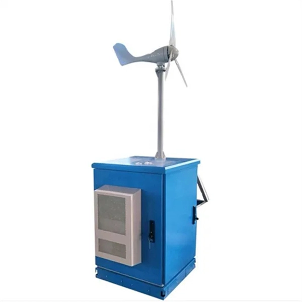
26 mm 2 (10 AWG) ground wire must be used, and in all other markets a 6 mm 2 must be used. On the US market, a 5. Each DISTRIBUTION BOX and controller must be grounded. Grounding of the units: Attach a ground wire from one of. Scaffoldings are grounded to ensure that any stray electrical current is safely diverted into the earth, preventing accidental electrocution, fire hazards, and static discharge on construction sites. This device safely takes power from a single source, such as a generator or temporary utility service, and divides it into. To ground a subpanel in a detached building, pull 4 conductors and separate the grounded and grounding bus. This part is covered by National Electrical Code article 250. Paragraph (d) of this section also applies to protective grounding of other equipment as required elsewhere in this Subpart.
[PDF Version]