-
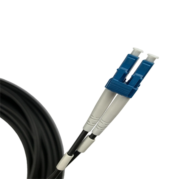
How to calculate patch cords for 4-core fiber optic cables
The fundamental calculation formula is: Total patch cords = Total number of device ports × Connection factor Where the connection factor depends on the connection method: 2. Scenario-Based Calculations The redundancy factor is typically 0 (no redundancy) or 1 (1:1 redundancy). Whether it's a data center, an upgraded telecom network, or designing FTTH systems, selecting the correct cable length ensures optimal. This article will walk you through the basics of fiber optic cores and provide practical guidance for selecting the suitable fiber optic cable to meet your networking needs. Fiber cores are the heart of fiber optic cables, transmitting light signals that carry data. Made from either high-quality. The number of optical cores in an optical fiber is the total number of equipment interfaces multiplied by 2, plus 10% to 20% of the spare quantity, and if the communication mode of the equipment has serial communication and equipment multiplexing, you can reduce the number of cores. These assemblies are widely used in ODN distribution frames, data center racks, MDU risers, and fiber management systems where higher.
[PDF Version]
-
How to calculate the number of fiber optic cables for users
The number of fiber strands is determined by the installation requirements, such as the number of switches or devices being connected and the type of application. This guide walks you through the simple decision steps engineers use, the common strand counts on the market, and clear rules-of-thumb for different project. This calculator keeps service strands, growth reserve, and spare capacity separate so the final cable count is easy to audit. Where is the cable going? Indoors or outdoors? Do you need singlemode or multimode fiber? How many fibers do you need in your cable? What length does the cable need to be? What connectors do you. A tool that computes how many fibers fit in a circular bundle and splits them into user-defined segments for cable-assembly planning. Key Parameters: • Center Diameter, Fiber Diameter, Packing Efficiency, Section Count Calculation: Visualization: • Color-coded radial diagram with per-section. Fiber optic network design refers to the specialized processes leading to a successful installation and operation of a fiber optic network. This helps reduce waste, manage costs, and achieve a clean, efficient installation.
[PDF Version]
-
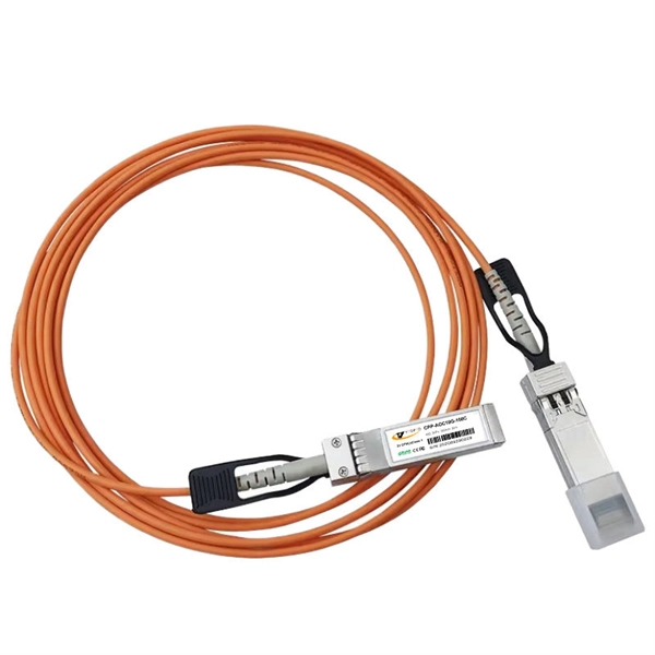
How much bandwidth can an aggregation switch handle
The USW-Aggregation switch can handle up to 160 Gbps of total non-blocking throughput, optimizing performance across all attached devices. By bundling multiple network connections into a single high-bandwidth link, aggregation switches help. An aggregate switch is a high-capacity network switch that consolidates connections from multiple access switches, acting as a central point for managing network traffic and providing enhanced bandwidth capabilities. It is essential for larger networks requiring efficient data flow. The core layer is the backbone.
-

How to calculate optical attenuation in communication optical cables
Optical attenuation compares input and output power on a logarithmic scale. When powers are in linear units, the loss in decibels is: Attenuation (dB) = 10 × log10 (Pin / Pout) If the link length L is provided, the attenuation coefficient is: Coefficient (dB/km) = Attenuation (dB) / L (km) For dBm. Signal attenuation refers to the progressive loss of signal strength as it propagates through a medium—whether free space, coaxial cable, or twisted pair. Use this Optical Fiber Attenuation Calculator to calculate total signal power loss through fiber optic cables using fiber length, attenuation coefficient, connector count, and splice count. Getting this right matters in telecommunications infrastructure, data center interconnects, and submarine. Explore the attenuation formula in optical fibres, factors affecting signal loss, and an example calculation for network efficiency. You can apply this methodology to all types of optical fibers in order to estimate the maximum distance that optical systems use. There are no specific requirements for this document.
[PDF Version]
-
How to calculate the number of cables a cable tray can hold
The formula used to calculate cable tray capacity is: Cable Tray Capacity = (Tray Width × Tray Depth × Fill Ratio) / Cable Cross-sectional Area Where: Tray Width is the internal width of the cable tray in meters (or millimeters). A Cable Tray Capacity Calculator is an essential tool for electrical engineers, contractors, and project managers involved in the installation and management of electrical cables. For mixed cables, sum the areas of all individual cables. Enter the dimensions of the cable tray, the desired fill ratio, and the diameter of the cables to calculate the cable tray capacity.
-

How to set up a network using a fiber optic panel
If your ISP doesn't require a technician to set up your connection, these are the steps to self-install fiber internet: Locate your fiber network terminal. Connect the fiber terminal to the network box. Once you understand the basic concepts, you can check out my Recommended Equipment section toward the bottom of the. This guide walks you through the complete fiber installation process, from checking availability to optimizing your Wi-Fi network performance. Fiber transmits data using light signals through glass strands, delivering faster speeds and lower latency than cable or DSL connections that rely on. However, setting up a fiber optic connection to your router can seem daunting if you're unfamiliar with the process. Jump to: How to. In this article we'll break down how fiber internet is installed - from the network fiber drop outside your house to the in-home setup with your router and gateway - and what you should expect at each stage. Fiber optic internet is generally installed in the following 5 steps, which we'll dive.
[PDF Version]
-
How much splitter loss is used to calculate optical power
Insertion loss tells you how much weaker the signal becomes after passing through the splitter. Let's say you have a laser output at 0 dBm (which is 1 milliwatt of optical power). Factors influencing splitter loss include splitter. Instantly compute insertion loss, power at each subscriber port, and fade margin for PLC and FBT splitters — including dual cascade configurations. Covers GPON (1490 nm / 1310 nm), EPON, and RF video overlay (1550 nm). Add connector and splice quantities with realistic planning losses. Enable power budget to estimate received power and margin. Splitters are essential when you want one fiber line from a central office (like an ISP's headend or data center) to serve multiple homes or businesses.
-
How to switch screens using the ReionalKVM switcher
Press the hotkey to switch between computers in full screen mode, or to switch the keyboard and mouse between computers in PIP or PBP modes. This article and video walk you through everything you need to set up a dual monitor KVM switch the right way—without guesswork or frustration. Is This the Right Setup for You? This article has been fully. A KVM (Keyboard, Video, Mouse) switch is an essential tool for anyone juggling multiple devices or systems while wanting the convenience of using just one keyboard, monitor, and mouse setup. 1 Front. How does my Dual Head KVM work? 3. How do I replace the F1DG102W wireless remote control? 4. us/081-HKU0202 Today's step-by-step KVM switcher setup video shows you how to connect 2 laptops with 2 shared screens.
-

How to calculate the size of a small electrical distribution box
The formula for calculating electrical box size is: [ BS = (N times D) + A ] Where: ( BS ) is the box size in cubic inches. ( N ) is the total number of conductors. This electrical box fill calculator (or in short, box fill calculator) will help you determine the total box fill volumes you will need to meet so that each of your electrical utility boxes will pass the National Electrical Code®. This guide explores the science behind determining the appropriate box size, providing practical formulas and expert tips to help you achieve accurate. Master electrical box fill calculations and ensure NEC compliance for safe and code-compliant electrical installations. Learn the principles, formulas, and best practices for proper wire management. ) Variables: To calculate the. Article Summary: Calculating the correct junction box size per the NEC 2023 involves a process known as a “box fill calculation,” primarily governed by NEC Article 314.
[PDF Version]
-
How to calculate the support structure for steel cable trays
Cable tray support quantity can be calculated using a simple formula: Support Quantity = Total Length ÷ Support Spacing + 1 20 ÷ 2 + 1 = 11 supports In a typical project, a 20-meter cable tray with 2-meter spacing requires 11 supports. As a key structure supporting the cable tray, the accurate calculation of the support quantity directly affects construction costs, efficiency, and safety. In complex engineering environments, the. This guide covers the critical steps, from selecting the right electrical cable tray and performing accurate cable fill calculations to managing a safe cable pull through and ensuring all bonding and grounding requirements are met. Ideal for electrical contractors and engineers. Classification of Loads Cable tray loads can be classified into the following categories: Dead Load (G): This. Correct sizing prevents sagging, overheating, and premature failure. You don't need a PhD—just a consistent method. This step‑by‑step approach helps you determine width, depth, support spacing, and allowable load with confidence.
[PDF Version]