-
How are the pins of the 2609B optical receiver module
With 900um-buffered single-mode fiber, without fiber connector. Internal current gain: 6 dB (typ. The 2609B is a packaged impedance-matched photodiode module with internal gain designed for use in optical broadband receivers in. The 2609B is a packaged impedance-matched photodiode module with internal gain designed for use in optical broadband receivers in fiber-optic networks. These are absolute stress ratings only. Functional operation of the device is not implied at these or any other conditions in excess of those given in the operational sections of the data sheet. Exposure to. no available.
-
How to determine light attenuation of red light using an optical power meter
Optical attenuation compares input and output power on a logarithmic scale. When powers are in linear units, the loss in decibels is: Attenuation (dB) = 10 × log10 (Pin / Pout) If the link length L is provided, the attenuation coefficient is: Coefficient (dB/km) =. Analyze optical power drop across fibers and links. Switch units, lengths, and calculation modes easily. Needed when attenuation is an. Optical power, required for measuring source power, receiver power and, when used with a test source, loss or attenuation, is the most important parameter and is required for almost every fiber optic test. Backscatter and wavelength measurements are the next most important and bandwidth or. Optical power meters are a key element in the optimization and maintenance of such optical networks and of their components. But, for designers, just starting to work in the fiber-optic design space, measuring attenuation can seem like a monumental task.
[PDF Version]
-
How to use an optical receiver
Find the **optical input port** on your audio receiver. An optical receiver is a device that converts light signals traveling through fiber optic cable back into electrical signals that electronic equipment can process. It's the endpoint of any fiber optic link, sitting at the far end of the cable and translating pulses of infrared light into the ones. In the world of home entertainment and audio systems, digital optical cables play a crucial role in delivering high-quality sound from one device to another.
-
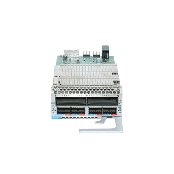
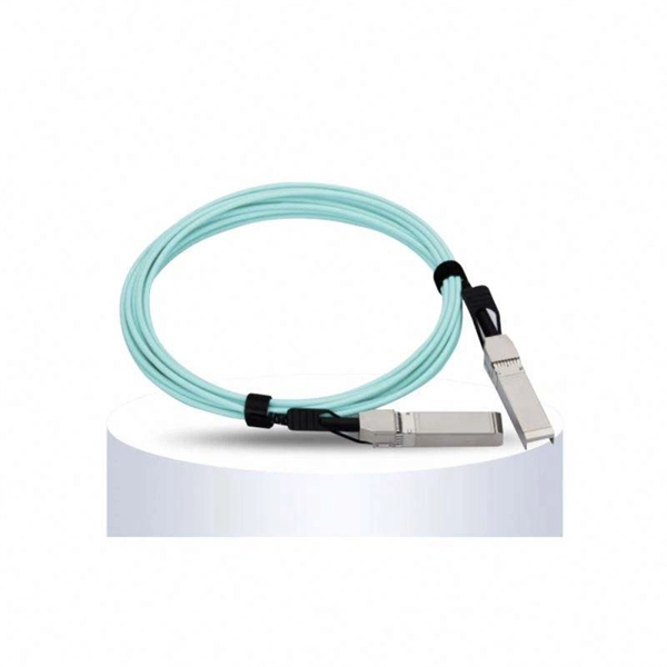
How to disconnect the fiber optic cable from a 40G optical module
To remove the cable, follow these steps: Attach an ESD-preventive wrist strap and follow its instructions for use. When pulling a cable from a transceiver, grip the body of the connector. If the cable does not remove easily, ensure that any latch present on the cable has been released before continuing. Whether you're upgrading bandwidth, replacing a faulty unit, or reconfiguring your topology, knowing. The modules are hot-swappable input/output (I/O) devices that connect the system's module port electrical circuitry with either a copper or a fiber-optic network. This document contains these sections: The 40-Gigabit QSFP+ transceiver module is a hot-swappable, parallel fiber-optical module with. Note: Before removing the dust plugs and making any optical connections, please remember the following guidelines.
-
How to transmit optical fiber over long distances
The core of a fiber optic cable is surrounded by a cladding, which reflects light back into the core, allowing it to travel over long distances with minimal loss. We live in a hyper-connected world where a video call with someone 10,000 miles away feels seamless. But how does light travel across oceans and continents with. Fiber-optic cables revolutionize long-distance data transmission using light, outperforming copper cables significantly. This exploration examines their workings, efficiency principles, and modern applications. Attenuation is the progressive loss of signal strength that occurs as light travels through the fiber. The greater the distance, the greater. The process of data transmission over optical fiber involves a series of conversions between electrical signals and optical signals: Signal Encoding: The initial digital data, typically represented as electrical pulses, undergoes encoding to optimize it for optical transmission.
[PDF Version]
-

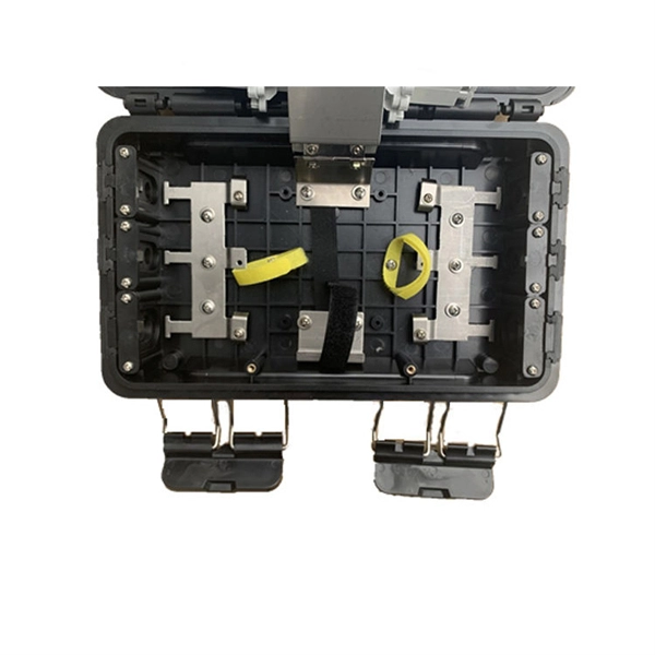
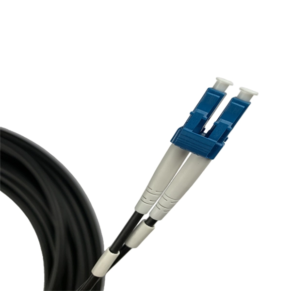
How to apply 8-core optical fiber cable to circuits
Learn how to splice fiber optic cable using fusion splicing with this complete step-by-step guide. Includes tools, best practices, loss standards (ITU-T G. 652), cost analysis, and FAQs for network engineers and installers. Regardless of the type of fiber network you're deploying, be it for telecom, enterprise data centers, or smart city infrastructure, fusion splicing provides the benefits of. Imm(branch cord)/2. Imm (main cord) Material Stainless Steel Color Silvery White UL94 V-0 (*Burning stops within 10 seconds on a veritcal specimen, no drips of flaming particles. ) *Exact product code is subject to the cable length. Specifications are correct at time of printing and subject. This article will guide you through the necessary tools, materials, and methods on how to connect fiber optic cables effectively, ensuring you achieve optimal performance from your fiber optic network. Have a network installation project? Fiber Optic Cables: The primary medium for your connections. The document also covers applications notes including the use of coupling coils and hardware recommendations for aerial installations. Question? Call 1-800-669-0808.
[PDF Version]
-
How to insert the Huijue optical module
Connect the XFP transceiver module to the network using an optical cable. After the optical cable is plugged into the transceiver, the LINK/ACT LED on the switch turns on. The following types of form. This section describes how to install an optical module. It is also prohibited to translate the document into other languages or use any or all parts of. P module is an input/output device that supports hot swapping.
-
How to use a cable locator to find optical cables
Cable locating equipment can help identify the exact location of buried fiber optic cables. Ground penetrating radar and electromagnetic field detection can help locate underground fiber. Fiber optic cables are critical components of modern communication infrastructure, often buried underground for protection and durability. However, locating these cables can be challenging without the right tools and knowledge. This guide will explain the most effective methods to locate buried. For locating purposes, the technician should first know if the fiber is armored with metallic shielding or unarmored without any type of metal built into the cable. Preparations before Locating III. When first introduced, it needed to do little more than find buried water, gas, or sewer lines. When you're digging or excavating on your private property, the last thing you want is to hit something important underground.
[PDF Version]
-
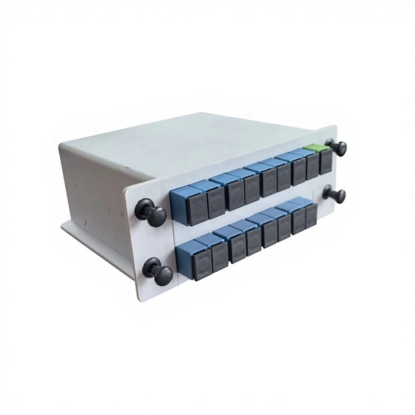
How much splitter loss is used to calculate optical power
Insertion loss tells you how much weaker the signal becomes after passing through the splitter. Let's say you have a laser output at 0 dBm (which is 1 milliwatt of optical power). Factors influencing splitter loss include splitter. Instantly compute insertion loss, power at each subscriber port, and fade margin for PLC and FBT splitters — including dual cascade configurations. Covers GPON (1490 nm / 1310 nm), EPON, and RF video overlay (1550 nm). Add connector and splice quantities with realistic planning losses. Enable power budget to estimate received power and margin. Splitters are essential when you want one fiber line from a central office (like an ISP's headend or data center) to serve multiple homes or businesses.
-
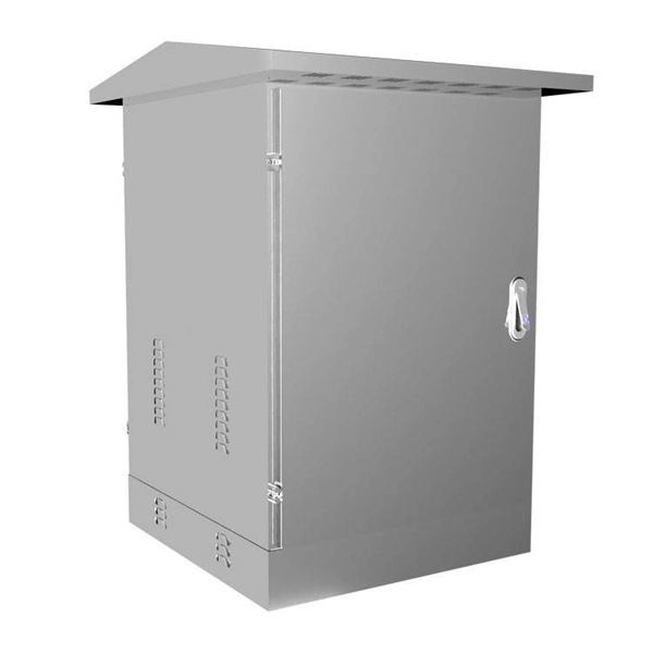
How much does a composite optical cable cost for home use
Prices vary based on the length of cable needed, installation method (aerial or underground), and labor rates in your area. Expect to pay $1 to $12 per linear foot, depending on project complexity and materials. Typical costs hinge on fiber count, indoor versus outdoor use, and whether trenching, splicing, or termination is required. This guide provides practical ranges in USD and practical price. We stock Composite Cable in a variety of gauge sizes. Labor dominates the installed price.
-
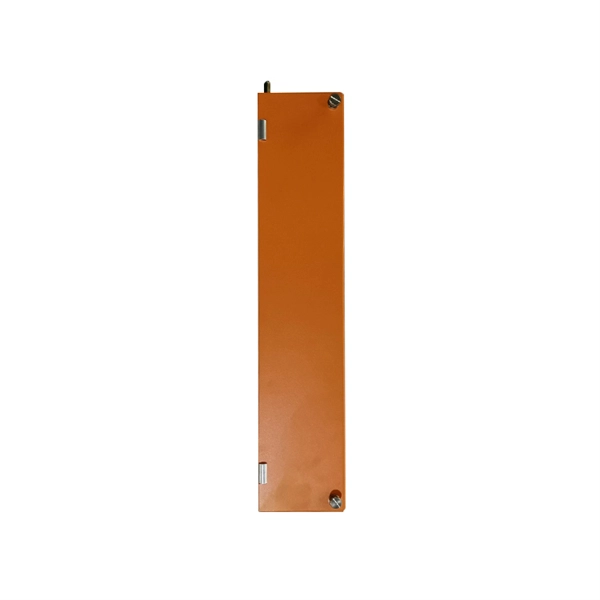
How to remove the finished optical module
To safely remove an SFP module, follow these steps: Disable the port in your network device settings or power off the device to avoid electrical damage. Gently pull the module latch or release ring, depending on the module design. Whether you're upgrading bandwidth, replacing a faulty unit, or reconfiguring your topology, knowing. Take ESD protection measures when replacing optical modules. Preparation Before Installation 1. more FS N5570-48S6C is a 48-port Layer 3 Ethernet switch with Broadcom Trident3-X5 chips, offering 1. They enable high-speed connections between active equipment and allow system scalability without the need for full infrastructure replacement.