-

How to connect the SD signal in the 19 optical module
The unit accepts one SDI signal on a BNC connector and provides one optical output of this signal on an ST connector over single-mode cable with a 1310 nm wavelength. solution for virtually any conversion you could need. Mini Converters convert analog to digital, digital to analog, SDI to audio, audio to SDI, up, down and cross conversion, SDI distribution, and can even provide a sync generator for lockin all your video equipment to the same reference signal. These transceiver modules are hot-swappable input/output (I/O) devices that plug into 100BASE, 1000BASE and 10GBASE ports (for SFP+), which connect the module port with the fiber-optic or copper network. If the optical module is installed on a GE port, run the display interfaceGigabitEthernet x/x/x command to view port information when the optical module. When the optical module on an interface is faulty, you can run the display commands to view information about the optical module. The notices referring to your personal safety are highlighted in the manual by a safety alert symbol, notices referring only to property damage have no safety alert.
[PDF Version]
-
10 Gigabit Ethernet card optical module not connected to fiber optic cable
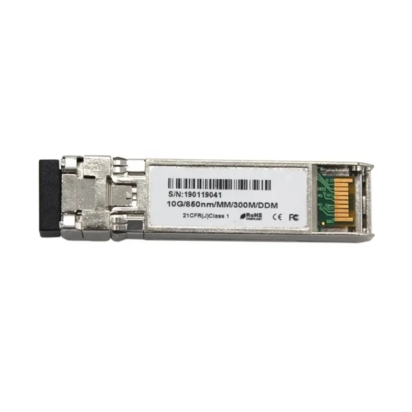
Troubleshooting SFP+ link issues in 10 GbE networks requires attention to module type, match of speed and wavelength, clean fiber connections, correct configuration, thermal management, and equipment compatibility. You can quickly resolve SFP+ Module connectivity issues by following a systematic optical transceivers troubleshooting process. Check for common connection problems, such as link failures or modules not recognized. Check compatibility between the optical module and switch Most switch brands have specific compatibility requirements. During network upgrades, many enterprise users encounter a common issue: after replacing 10G broadband lines or inserting 10G SFP+ optical modules, the switch still fails to operate at full 10G bandwidth or even fails to recognize the modules. We've listed the five most common ones. First of all, let's briefly recap what SFP and SFP+ stand for. SFPs – short for 'small form-factor pluggable' – are compact, hot-pluggable devices.
[PDF Version]
-

How to connect the 10 Gigabit Ethernet cable to the fiber-to-electrical port module
A special 10G Copper RJ-45 Transceiver (10G-SFP-T) is required to connect the SFP+ port to RJ45. It allows connecting a server/storage side Cat6/7 cable to an SFP+ port transceiver. An SFP module (or optical transceiver) converts electrical signals from network devices (switches, routers) into optical signals for fiber transmission and vice versa. 1G/10G SFP+: Standard for Gigabit and 10 Gigabit Ethernet. These transceiver modules are hot-swappable input/output (I/O) devices that plug into 100BASE, 1000BASE and 10GBASE ports (for SFP+), which connect the module port with the fiber-optic or copper network. 4ft (30m) * using Cat6a/Cat7 or above cable for 10G connection in various applications. In this video, we'll guide you through building a high-speed 10G LAN by connecting two fiber switches. Finally, check the transmit (TX) and receive (RX) paths to ensure that signals are aligned.
[PDF Version]
-
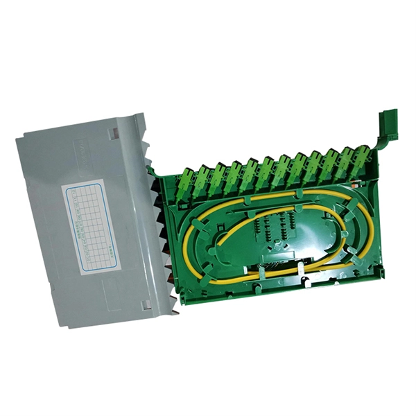
How to remove a loose pull ring from an optical module
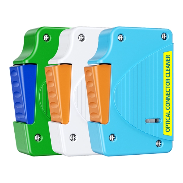
Gently pull the module latch or release ring, depending on the module design. To use an SFP optical module, first confirm that the host port is SFP-type. Figure 1 SFP Optical Module Installation. However, with the right approach and careful handling, you can safely remove a transceiver stuck in a switch without causing damage to your network equipment. There are two primary reasons why an SFP module might become stuck in a port: The SFP is wedged in the cage: This can occur due to slight. To connect an optical cable to an SFP module, use the appropriate patch cord (e. Once connected, verify that the port activity indicator is on and run diagnostic commands to check the module status. After removing the fiber jumper, insert a clean dust cover over it to protect the end face of the module.
-
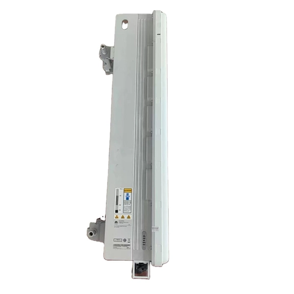
RRU optical module location
RS can be installed in a suitable machine room location, and RRU is installed at the antenna end. By separating RS from RRU, the tedious maintenance work can be simplified to the RS end. AAU, RRU, and BBU are key components in a telecom network, particularly in modern wireless communication systems like 4G and 5G. Here's a breakdown of each: The central processing unit in a base station. Usually. Optical modules used in Remote Radio Units (RRUs) for CPRI applications are required to support industrial temperature ranges, primarily because RRUs operate in diverse outdoor environments with extreme temperature variations. CPRI (Common Public Radio Interface) defines the interface relationship. RRU is short for remote radio unit. Strip the jacket off the RRU power cable for a small part, press the exposed shielding layer on the strap, and then connect the PGND cable on the strap to the nearest grounding bolt on the side in the. The mode. Determine a position for installing 2. Loosen the two M10 nuts on the mounting M10 bolt from the U notch.
[PDF Version]
-
How to enable the optical module after plugging it into the optical port
Align the SFP module with the optical port and insert it horizontally, pressing firmly until the bottom of the module engages with the locking spring of the optical interface. Figure 1 SFP Optical Module Installation. The Cisco Small Business Series Switches allow you to plug in a Small Form-factor Pluggable (SFP) transceiver in their optical modules to connect fiber optic cables. Once the transceiver and fiber optic cable are plugged in properly in the switch optical module, you should be able to view the. This section describes how to install optical transceivers on the SFP or SFP+ ports and connect them to the ports of the peer device using optical fibers according to the network plan. The USG supports both 1 Gbit/s, 10 Gbit/s, and 40 Gbit/s optical modules. The LED will only light up when all connections are properly established and functioning correctly. The installation process can be taken by the following instructions.
[PDF Version]
-
Increase the light output power of the optical module
An optical amplifier is a device which receives some input signal light and generates an output signal with higher optical power. Typically, inputs and outputs are laser beams (very rarely other types of light beams), either propagating as Gaussian beams in free space or in a fiber. At the receiver end, the optical signals are reconverted into electrical. In this guide, we will explain what optical signal strength is, how to check it on Cisco IOS using the command line, and how to troubleshoot common light level issues. Assume the. This application note gives a short introduction to optical modules and the need of an optimized power tree in them and then concentrates on the use cases and benefits of four-switch and inverting buck-boost converters inside optical modules.
-
Gocent optical module
Coherent optical module refers to a typically hot-pluggable coherent optical transceiver that uses coherent modulation (BPSK/QPSK/QAM) rather than amplitude modulation (RZ/NRZ/PAM4) and is typically used in high-bandwidth data communications applications. Optical modules typically have an electrical interface on the side that connects to the inside of the system and an optical int. Electrical Interface TypesThere are multiple variants of the electrical interface of coherent optical modules use. The in 2016 published the CFP2-ACO or CFP2 - Analog Coherent Optics Module Interoperability Agreement. Many different forms of optical modulation and multiplexing have been employed in coherent optical modules. Some coherent optical modules can fall back to older, simpler modulation techniques.