-
Should grounding flat iron be placed in cable trays
Where cable tray systems contain only signal and communication circuits that operate at low energy levels, power grounding per NEC Section 318-7 is not appropriate, but cable tray grounding for lightning protection, noise, and electromagnetic interference is necessary. Cable tray may be used as the Equipment Grounding Conductor (EGC) in any installation where qualified persons will service the installed cable tray system. 8, 11, and 12, and the National Electrical Code Sections 318-3-© and 318-7. It is also covered in NEMA Standard VE-2. The purpose of power grounding (Article 250) is to minimize the damage from wiring or. Grounding and bonding are mandatory for metallic trays. Tray fill limits must be calculated properly. Power and data cables require proper separation.
-
What is the spacing between flat cable tray supports
For horizontal sections where cable trays are laid out in a straight line, the typical support span (distance between supports) should range from 1. This range allows for easy access and efficient maintenance. Proper installation can significantly reduce electromagnetic interference, prevent fire hazards, and improve overall efficiency. This article provides an in-depth. An electrical cable tray system serves as a rigid structural raceway designed to support and route electrical cables and wires. Unlike a simple wire trough, which is typically a covered channel for shorter runs, cable trays provide a comprehensive support system for complex wiring paths over long. Hubbell's NEXTFRAME® Ladder Tray is the effective and widely used cable runway that supports and delivers bundles of cable between cabinets, racks, and closets, along walls, and suspended from ceilings. A rung spacing of 6 to 9 inches (150 to 230 mm) is preferable when.
[PDF Version]
-

How much distance should the cable tray support be installed
Generally, standard trays require supports every 6 to 10 feet, while heavy-duty, long-span trays can handle distances of up to 20 feet between supports. To determine the proper spacing, consult the manufacturer's load capacity chart, which accounts for the total weight of the. The NEC requires that cable trays must be supported by members at an interval specified by the cable tray manufacturer, but not more than 5 feet for horizontal runs to support the weight of the cables and other loads. The NEC has a requirement for ladder-type cable trays. This spacing is crucial for adequate maintenance access, ease of inspection, and ensuring proper airflow for effective heat dissipation. Support Methods: Common support methods include trapeze hangers, which are. This is a description of how to select, install, and support these metal or plastic frames, on which electrical wires are installed.
[PDF Version]
-
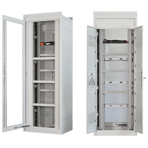
Are ladder racks used as support frames for cable trays
Ladder rack (also known as “ladder trays” or “cable ladders”) are one of the most common types of cable runway. As the name suggests, they're constructed of two side rails connected by rungs, creating an open structure for cable support and management. Whether suspended from the ceiling, wall-mounted, or supported by racks and cabinets, overhead cable management systems are flexible and scalable. They can easily be moved, reconfigured, or expanded as needed to meet changing requirements and evolving connectivity needs.
-

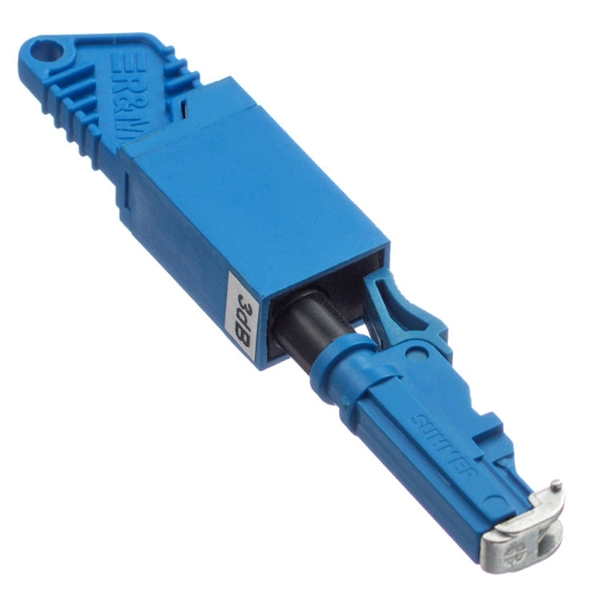
Composition of butterfly-shaped drop fiber optic cable
FTTH Butterfly Optic Cables, also known as flat drop fiber cables, feature a compact flat profile with optical fibers placed at the center and reinforced by parallel strength members on both sides. Then, the cable is completed with LSZH sheath. Also, customers can specify your required connectors. Environmental Performance. Abalone Tech's 1/2/4F Self-supporting Butterfly Drop Cable is designed for aerial and duct installations in FTTH (Fiber-to-the-Home) and telecom networks. 5 kg/km Optical Performance: Insertion loss <0.
-
Requirements for Outdoor Drop Cable Laying
This definitive guide covers the key requirements for height, spacing, structural loads, and materials. Ensuring your cable railing is up to code in California not only tells you that it was properly installed by a competent crew, but also increases the safety of you and your family when spending time near your railing. In general, if your deck or balcony is more than 30 inches above the ground, a. Service loops are essential for maintenance. Leave about 100 feet of extra cable per 1,000 feet, and add loops at street crossings. 12) All 15- and 20-amp, 125-volt outdoor receptacles must have GFCI protection. Exception: Some snow-melting or deicing. This involves locating existing pathways, identifying potential obstacles, and measuring distances to ensure cables stay within the 100-meter limit for optimal performance. Installation Methods Compare Direct cable is a simple solution for fiber drop cable installation.
[PDF Version]
-

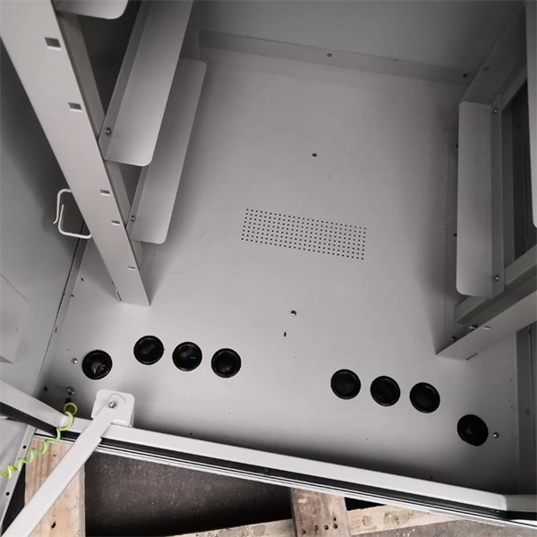
Cable tray support width is two meters
Cable tray support quantity can be calculated using a simple formula: Support Quantity = Total Length ÷ Support Spacing + 1 20 ÷ 2 + 1 = 11 supports In a typical project, a 20-meter cable tray with 2-meter spacing requires 11 supports. Cable tray supports are components used to fix and support. In practice, cable tray dimensions are a system of interrelated measurements —width, depth, length, and material thickness—that directly affect cable fill compliance, heat dissipation, structural loading, and long-term expandability. Tray Depth is the internal depth of the cable tray in meters (or millimeters). International projects are most often made in widths of between 50mm and 900mm and depths of between 50mm and 150mm. You don't need a PhD—just a consistent method.
-
How far apart should the cable tray be placed with its fixed support
Support spacing for cable trays must align with the manufacturer's instructions, as outlined in NEC 392. Generally, standard trays require supports every 6 to 10 feet, while heavy-duty, long-span trays can handle distances of up to 20 feet between supports. The NEC has a requirement for ladder-type cable trays. This is a description of how to select, install, and support these metal or plastic frames, on which electrical wires are installed. You should consider it as a series of instructions that make the buildings resistant to. When installing two cable trays in parallel at the same height, the distance between them should be no less than 0. But it's also important to minimize.
-
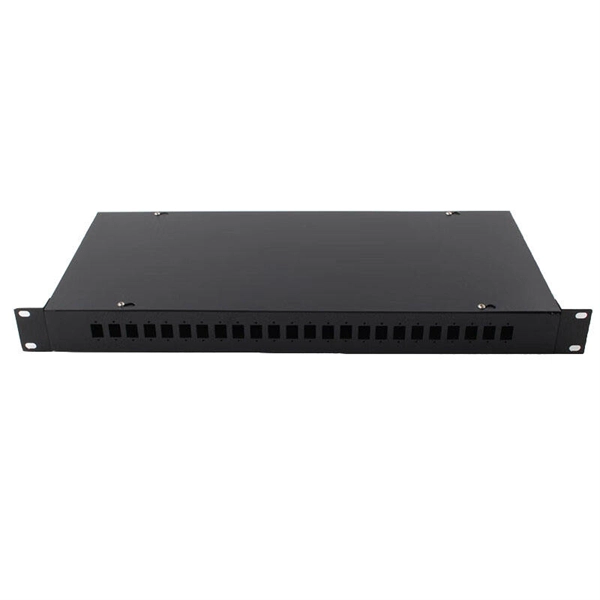
Fiber optic cable connected to router then connected to switch
If using a network switch with SFP ports, insert the fiber optic transceiver into the SFP port and connect the fiber optic cable to the transceiver. Connect the other end of the Ethernet cable to your network device, such as a computer, router, or. Fiber Optic Transceiver: Often used with media converters or network switches, these devices convert electrical signals to optical signals and vice versa. Patch Panel. As we speak I just have optic fibre (Community Fibre) connected to my Huawei modem / Linksys Velop which will be connected to a new POE switch (need to identify the best model to be compatible with my optic fibre extension project). Network topology refers to the way in which the links and nodes of a network are arranged in relation to each other. Use a standard Ethernet cable (Cat5e/Cat6) to.
[PDF Version]
-

What does a 72-core optical cable look like
GYTA53 fiber cable consists of 250um fibers held in gel-filled PBT loose tubes, and wrapped around a phosphatized steel wire central strength member. A waterproof compound fills the loose tube, and the center of the cable core is a metal reinforced core. 72 core fiber optic cable should be selected by fiber standard, cable structure, jacket, tensile strength, installation route, drum length, testing, and quantity. single mode GYTA53 fiber optic cable and multimode. Fibertronics' Fiber Optic Distribution Cable is composed of high quality colored tight buffers, aramid yarn and a PVC outer jacket. Their small bend radius allows for fast installations and easy terminations within confined. Corning ribbon plenum cables are designed for use in plenum, riser and general purpose environments for intrabuilding backbone installations and for high-fiber-count data centers.
[PDF Version]