-

How to connect the 10 Gigabit Ethernet cable to the fiber-to-electrical port module
A special 10G Copper RJ-45 Transceiver (10G-SFP-T) is required to connect the SFP+ port to RJ45. It allows connecting a server/storage side Cat6/7 cable to an SFP+ port transceiver. An SFP module (or optical transceiver) converts electrical signals from network devices (switches, routers) into optical signals for fiber transmission and vice versa. 1G/10G SFP+: Standard for Gigabit and 10 Gigabit Ethernet. These transceiver modules are hot-swappable input/output (I/O) devices that plug into 100BASE, 1000BASE and 10GBASE ports (for SFP+), which connect the module port with the fiber-optic or copper network. 4ft (30m) * using Cat6a/Cat7 or above cable for 10G connection in various applications. In this video, we'll guide you through building a high-speed 10G LAN by connecting two fiber switches. Finally, check the transmit (TX) and receive (RX) paths to ensure that signals are aligned.
[PDF Version]
-
10 Gigabit Ethernet card optical module not connected to fiber optic cable
Troubleshooting SFP+ link issues in 10 GbE networks requires attention to module type, match of speed and wavelength, clean fiber connections, correct configuration, thermal management, and equipment compatibility. You can quickly resolve SFP+ Module connectivity issues by following a systematic optical transceivers troubleshooting process. Check for common connection problems, such as link failures or modules not recognized. Check compatibility between the optical module and switch Most switch brands have specific compatibility requirements. During network upgrades, many enterprise users encounter a common issue: after replacing 10G broadband lines or inserting 10G SFP+ optical modules, the switch still fails to operate at full 10G bandwidth or even fails to recognize the modules. We've listed the five most common ones. First of all, let's briefly recap what SFP and SFP+ stand for. SFPs – short for 'small form-factor pluggable' – are compact, hot-pluggable devices.
[PDF Version]
-
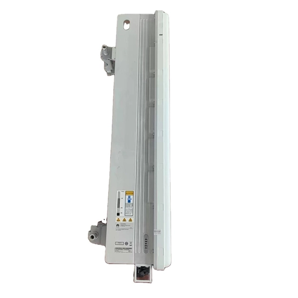
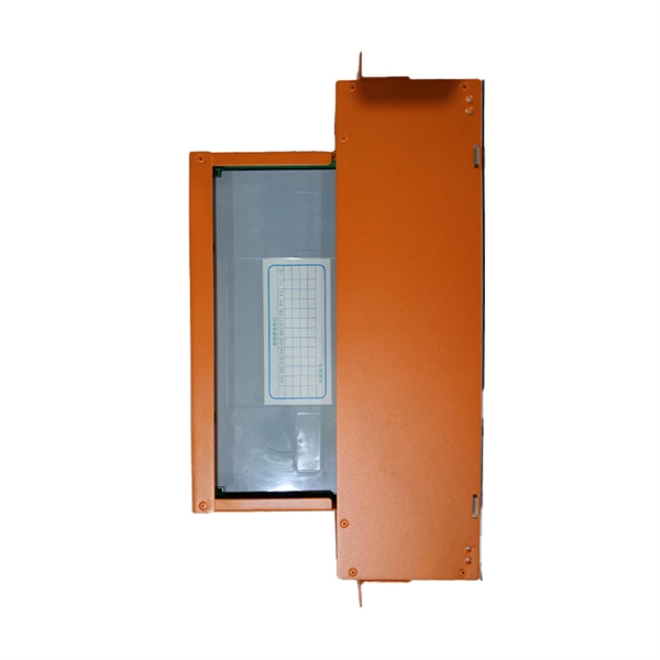
Inspect the power distribution box switch box for faults
Check the electrical load and ensure that the sensors do not exceed the 10 Amp maximum. Power distribution & circuit protection depend on it. LV intrusive switchboards accept power from the utility & generator & distribute it to building circuits. Ensure that all labels and warning signs are legible. Internal Inspection Open the distribution box and check for. Diagnose the fault in a low voltage distribution box by checking for overheating, loose connections, and using voltage testers for safe troubleshooting.
-
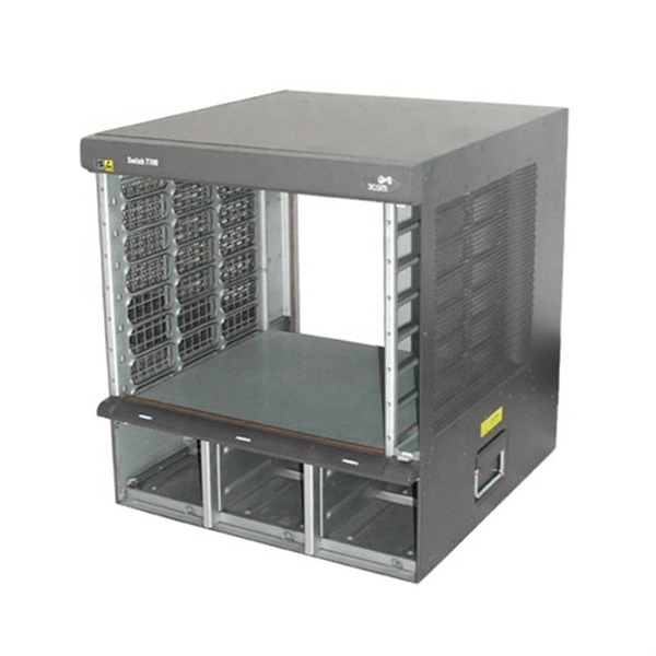
Huawei Terminal Switch Access Devices
The terminal access allows Ethernet access using LAN switches, WLAN access using APs, and asymmetric digital subscriber line (ADSL) access using digital subscriber line access multiplexers (DSLAMs). This document describes the Huawei Terminal Access Controller Access Control System (HWTACACS), including the relationship between TACACS, TACACS+, and HWTACACS, the compatibility between HWTACACS and TACACS+, the comparison between HWTACACS and RADIUS. After a while HWTACACS has became a standard protocol that is supported by all vendors. If you would like to learn more on RADIUS. SNMPWalk: SNMPWalk is a command-line tool that utilizes Simple Network Management Protocol (SNMP) to retrieve information from network devices. It can be used to gather data from Huawei switches, such as interface statistics, VLAN information, and system details. It supports access of 100 to 500 terminals of a small-sized enterprise to the NMS, and applies to scenarios of terminal address assignment and terminal user.
[PDF Version]
-
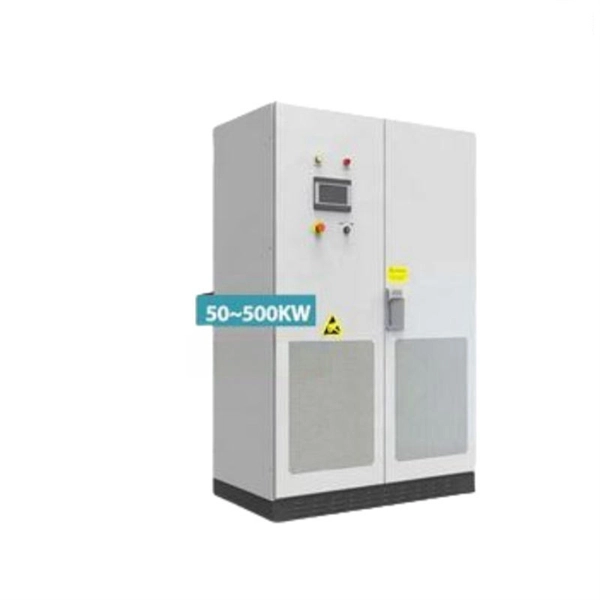
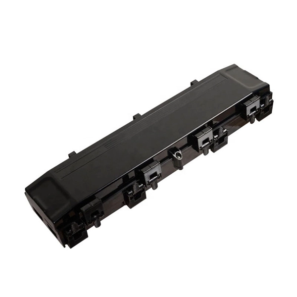
Secondary distribution box main switch
Secondary selective service achieves similar results by using switches on secondary voltages rather than primary voltages. With secondary selective service, each distribution transformer must be a.
-
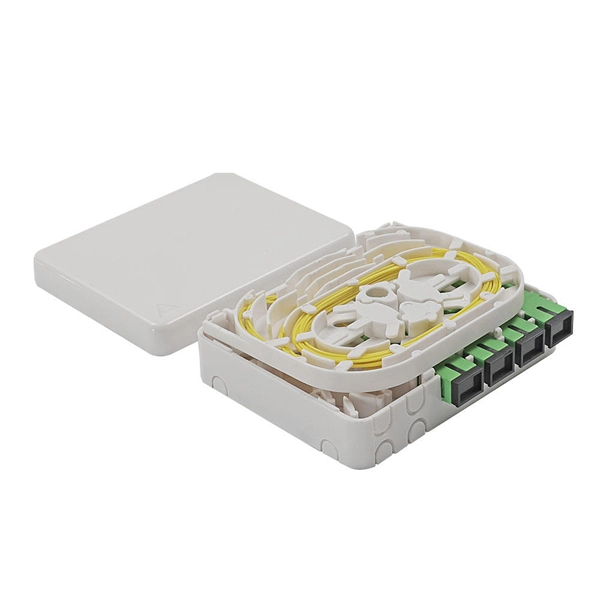
How many cascading levels does a fiber optic switch support
The switch connected to the switch is called cascade. However, in the actual application process, it is recommended that the cascade does not exceed four layers. Cascading can be defined as two or more switches. This guide focuses on two critical aspects of optical splitters that define FTTH performance: split ratios (how signals are divided) and splitting architectures (how splitters are deployed). A key challenge is determining how many users a single OLT port can support, which is defined by the split ratio. Traditional GPON networks often employ 1:32 or 1:64 splits. The connection between two or more Ethernet switches in a certain way (Uplink port, etc. Multiple switches can be cascaded in various ways according to. On the other side of the splitter, 32 fibers are routed through distribution panels, splice ports and/or access point connectors to 32 customers' homes, where it is connected to an optical network terminal (ONT).
[PDF Version]
-

Connect the pigtail directly to the switch
Connect the pigtail wire to the electrical outlet or end device by tightening it with a screw. But you have to loop the bare wire around the screw terminal first. This article will discuss what an electrical pigtail is, the tools and materials you need, and the step-by-step process. What's a pigtail & how to connect is what this DIY howto video is about. VideoJoe is right in the middle of wiring up a new 2gang cutin electrical outlet wall switch box & he wants to show you what a pigtail is & why he needs to connect up an electrical pigtail in order to get both his ex. Also, it can join several wires to become a single conductor for electrical connections. Likewise, the source hot is removed from the receptacle and spliced to the new.
-
Delay of Direct Connection to Normal Access Switch
Verify signal strength (-14. Data Link Layer: Confirm VLAN tagging (802. Ensure VLAN IDs match and clear ARP cache if needed. This document describes common LAN switch features and how to troubleshoot any LAN switching problems. There are no specific requirements for this document. The sections in this chapter describe common LAN. The following troubleshooting information can help you diagnose and fix issues with your Direct Connect connection. If you've got a moment, please tell us what we did right so we can do more of it. However, when issues arise, troubleshooting can be complex, as problems may occur across multiple layers: physical, data link, network/transport, and routing. Note: It's a best practice to set up an on-premises dedicated test machine with an Amazon Virtual Private Cloud (Amazon VPC).
-
PoE switch line short circuit
Unplug the POE from the power outlet it is plugged into. Unplug the line that comes in from outside that is plugged into the “POE” port and is labeled “To Radio” Check the ethernet end and POE port for evidence of marring, discoloration, moisture, or foreign debris. This isn't an exaggeration; it's a real hardware disaster that can occur and requires serious attention. What adverse events can occur when a PoE port short-circuit occurs? A short circuit can happen in a PoE device's network. As part of the build, I installed a new Brocade ICX 6450 switch to power phones and provide data. Cut to last week while I was on vacation. " The Ex4300-48MP switch Power over Ethernet (PoE) has stopped working and is not supplying power to some ports. POE reduces the number of cables needed to connect networked devices and enables systems to access locations where power is not readily.
[PDF Version]
-
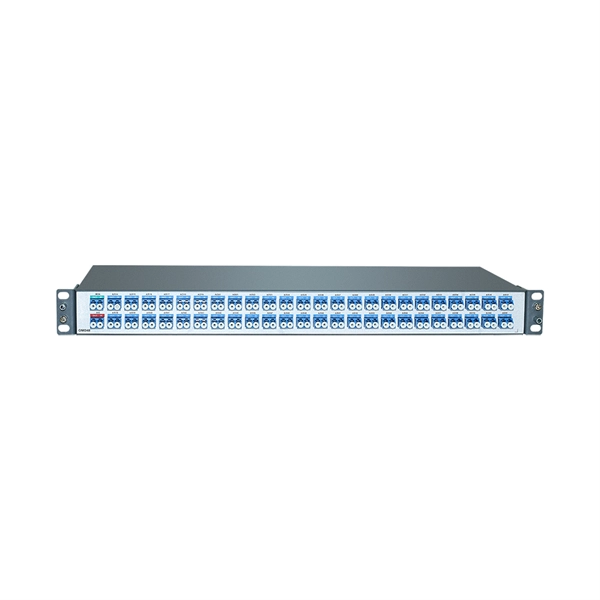
One-optical-four-electrical-system small switch
The Mini 1×4 fiber optic switch connects optical channels by redirecting an in- coming optical signal into a selected output fiber. Latching operation preserves the selected optical path after the drive signal has been removed. Find out what's included and explore available upgrade options from Keysight. Its dimensions are as small as 38x27x8. It can be used as 1 input to 4 outputs or 4 inputs to 1 output. Features:. Optical switch (or fiber optic switch) can be a mechanical, opto-mechanical, or electronic device that opens or closes an optical circuit.
-

What is a two-optical switch
The basic form of an optical switch is 2×2, which means there are two optical fibers at both the input and output ends. This technology allows for high bit rate transmission to be switched between various optical lines. However, more advanced devices can route one. Optical Switches, or optical switches, are devices that have one or more selectable transmission windows and can perform mutual conversion or logical operations on optical signals in optical transmission lines or integrated optical paths.
-
Switch cabinet busbar installation
In North America, follow UL 891 construction and NEC Article 408 installation practices: use listed/approved hardware, lugs, or tap-off provisions intended for the bus. The matrix below helps engineers finalize material, arrangement, plating/insulation, and verification. The GRL busbar system makes distribution cabinet installation fast, flexible, and neat. At this stage, the supports have been installed in accordance with the installation plan. Ever wondered how busbars, the unsung heroes of electrical distribution, are processed and installed? This article delves into the intricate steps of busbar selection, preparation, and installation, ensuring efficient and safe power distribution. The application of these rules means strict compliance, not only with applicable regulations and standards, but also with manufacturers'. Bus bars play a crucial role in electrical distribution systems by providing a reliable and efficient way to conduct electricity within electrical panels.
[PDF Version]