-
Budget for underground optical fiber cables for railway communication
Armored fiber optic cables designed for direct burial cost $6-14 per linear foot. Conduit systems add $2-4 per foot but allow future cable additions. These fiber cables connect and transmit real-time data to the ROC for signaling and train control, train movements, traction power substation systems, passenger. Our RDSO-approved Armoured Optical Fiber Cables are engineered for high-performance underground installations in railway signaling and telecom networks. Compliant with IRS:TC 55-2006 Rev. 2 meters (3-4 feet) deep to reduce the likelihood of accidentally being dug up. In extreme cold climates, cables may need to be buried at greater depths where there temperatures are colder and frost penetrates to. The Federal Railroad Administration (FRA) sponsored an evaluation conducted by Transportation Technology Center, Inc. regarding the opportunity and availability to use Fiber Optic Acoustic Detection (FOAD) in the North American railroad industry.
[PDF Version]
-
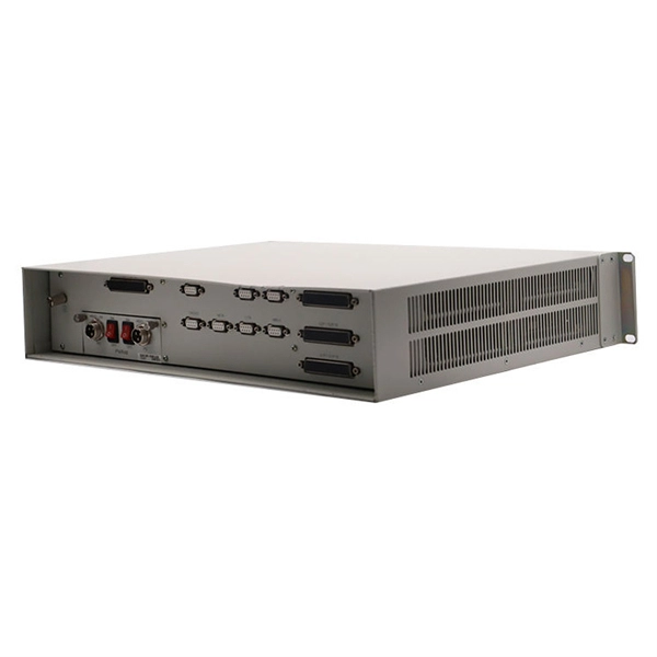
Mobile Communication Equipment Room Construction Costs
The physical cost of building a cell tower, including the necessary passive infrastructure, generally requires only a few components: As shown above, the tenant, which can be a wireless carrier like Veriz.
-
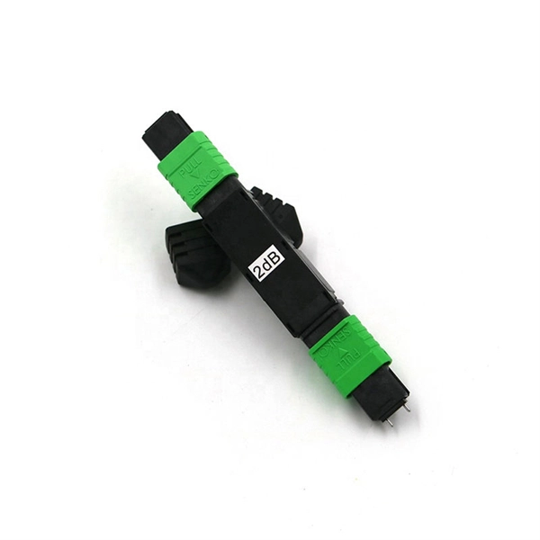
Intelligent Customization Process for MTP Adapter Modules for Railway Communication
Klaus Lechtenbörger from EPLAN shows how P&ID flow diagrams can be created efficiently in the MTP tool chain and exported as MTP. Laurids Beckhoff guides you through the process of module definition and development along with automatic PLC and human-machine interface. The Module Type Package (MTP) is a concept that allows process technology plants to leverage maximum potential across the board, from the planning phase through to operation. This makes MTP a crucial component in the development of future modular automation solutions. 0 as new consistent set of documents! Member Review for MTP Specification part 1 has been kicked off on June 12, 2024 After the initial release, a release of the MTP Specification is planned every 2 years. What is MTP? In many places, the process industry is characterized by large systems that have been in operation continuously. MTP is a description semantic – comparable to a device driver – with the help of which your system, laboratory or technical center can be reconfigured quickly and easily. Plug & Produce enables modules and devices to be integrated as easily as a printer with a PC.
[PDF Version]
-
How to locate the fault point in a communication optical cable
Struggling to identify faults, validate polarity or ensure quality mechanical connector terminations in your fiber optic cables? Visual Fault Locators (VFLs) are a valuable tool that make troubleshooting fast and efficient. Let's dive into everything you need to know about mastering VFLs. Common Indicators of a Cable Break Signal Loss or Interruption: If data transmission is interrupted, it could indicate a break or severe bend. Physical. Finding a fiber fault typically involves the following steps: 1. However, physical damage can disrupt this infrastructure and cause significant network issues. When fiber cables sustain damage, specialized repair techniques help. To ensure the quality and continuity of fiber optic services, it is essential to identify and locate fiber optic cable faults as quickly and accurately as possible.
-
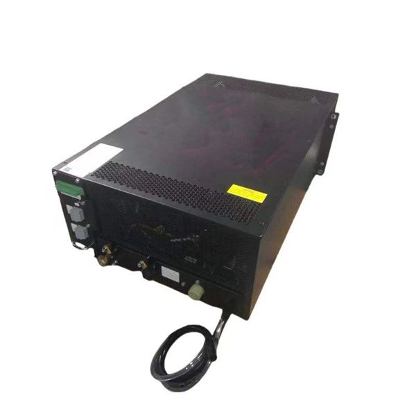
Principle of Fiber Optic Communication Spectrum Analyzer
These instruments are used to measure wavelength emissions from Lasers, Laser Diodes and LED's into the near infrared. From detecting signal distortions to optimizing optical. Optical spectrum analyzers are specialized instruments that measure light intensity as a function of wavelength. The COSA-4055 module offers the functionality and speed of an OSA in a handheld form factor at a fraction of. E/O converters use light-emitting elements such as semiconductor lasers, O/E converters use light-receiving elements such as photodiodes, and optical elements such as lenses are used at the input and output of optical fiber.
-
What are the requirements for laying fiber optic cables for communication in Zimbabwe
163 describes criteria for the installation of optical fibre cables defined in Recommendation ITU-T L. (FOA) was founded in 1995 to help develop the workforce to build the fiber optic networks to support a rapid expansion in communications and the Internet. From the initial site survey to the final fiber to the home (FTTH) connection, every stage requires careful planning, coordination, and. Underground cables are pulled in conduit that is buried underground, usually 1-1.
-
Optical communication products specifically refer to
Modern communication relies on optical networking systems using optical fiber, optical amplifiers, lasers, switches, routers, and other related technologies. Optical communication, also known as optical telecommunication, is communication at a distance using light to carry information. It can be performed visually or by using electronic devices. The earliest basic forms of optical communication date back several millennia, while the earliest electrical. Therefore, NASA is developing optical communications to address limitations of radio frequency (RF) communications, including: bandwidth, spectrum and overall size of frequency packages and power used.
-
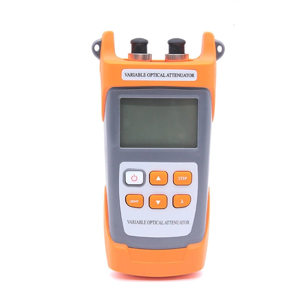
Incident Power in Fiber Optic Communication
The incident optical power is used to suppress nonlinear effects and ensure transmission quality. In the following figure, optical power at point C is the incident optical power. Why Do We Need Incident Optical Power? The transmission performance of a WDM system is affected by the. This AE Note explains the differences between Optical Return Loss (ORL) and Back Reflectance in fiber optic systems. Even minor deviations—whether too high, too low, or unstable—can impact signal integrity, trigger service alarms, or interrupt traffic on DWDM, OTN, or long-haul optical line systems.