-

Analysis of the causes of signal attenuation in optical splitters
In the context of beam splitters, attenuation can occur due to several factors, including absorption, reflection, and scattering. Understanding how beam splitters affect signal attenuation and polarization is essential for optimizing systems in telecommunications, imaging, and laser applications. In the. Fiber optic splitters distribute optical power from one input fiber to multiple output fibers through either fused biconical taper (FBT) coupling or planar lightwave circuit (PLC) waveguide structures. Their performance depends on optical symmetry, waveguide integrity, and mechanical stability of. · Signal Attenuation: The loss of signal strength as it travels through the fiber can lead to poor quality communication. By careful processing, couplers that were bidirectional were made. So a 2:2 coupler would take the signal from one fiber on one side and split it between the two fibers on the.
[PDF Version]
-
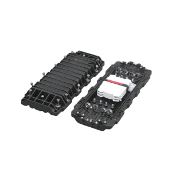
Optical splitters are divided into box-type and
Optical splitters can be divided into two types based on their working principles: Planar Lightwave Circuit (PLC) optical splitters and Fused Biconic Tapered (FBT) optical splitters. Optical splitters are a very important component in fiber optic links, widely used in. A fiber optic splitter is a passive optical component that divides a single incoming optical signal into two or more outgoing signals, or combines multiple incoming signals into one.
-
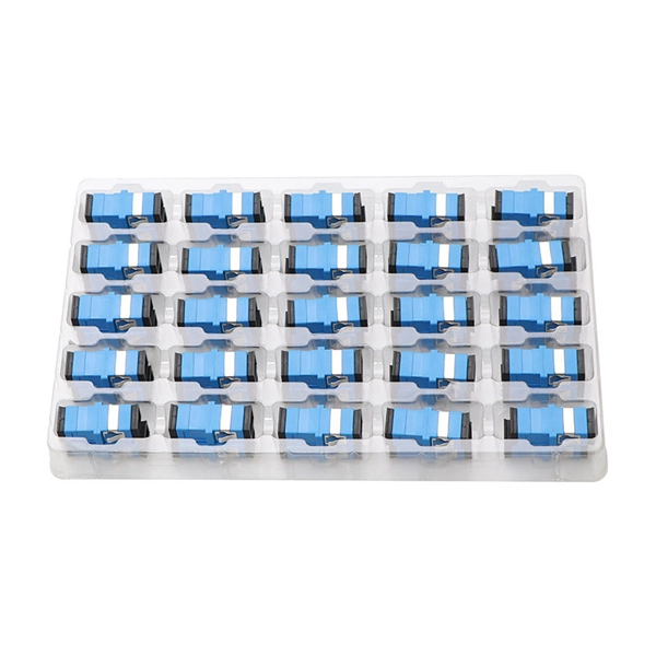
Four types of optical splitters
There are several types of fiber optic splitters, each with its unique characteristics and applications. Whether you're a network engineer designing a PON (Passive Optical Network) or a homeowner curious about how your fiber connection works. Fiber optic splitter is a passive optical device used to distribute optical signals, which can divide input optical signals into multiple outputs to meet the fiber optic access needs of multiple terminal devices. Conversely, it can also combine multiple signals into one. What Is an Optical Splitter Fiber and Why Do You Need One? At its core, an optical splitter fiber is a device. Splits are most commonly factors of 2, such as 1x2, 1x4, 1x8, 1x16, 1x32, 1x64, etc. More recently, odd split ratios such as 1x3, 1x5, etc have found some use.
-
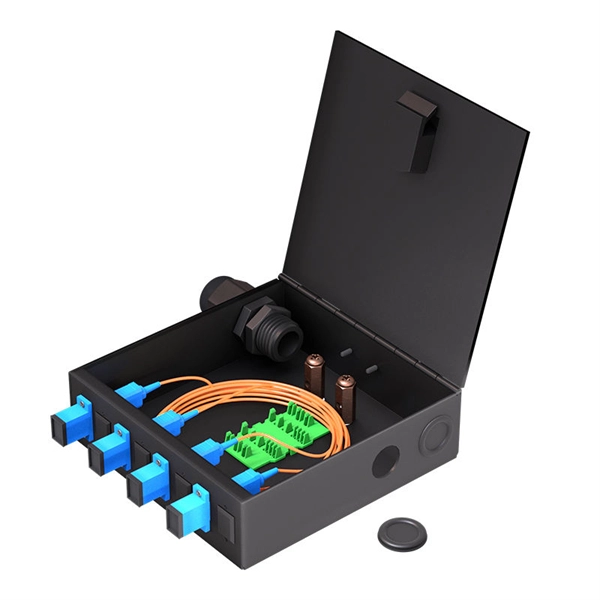
The function of a 10 Gigabit optical splitter
By dividing a single optical signal from a central Optical Line Terminal (OLT) into multiple outputs for Optical Network Terminals (ONTs) at users' homes, splitters eliminate the need for dedicated fibers to each residence—slashing infrastructure costs while scaling network reach. An Optical Splitter, also known as a beam splitter, is a passive optical device that divides a single input optical signal into two or more output signals. Conversely, it can also combine multiple signals into one. Optical splitter. Where splitters are placed in the network can make significant impacts on fiber counts, network cost and deployment time and operational steps, such as customer onboarding and maintenance. One important note is that splitting architectures should be seen as tools that can be mixed and matched to. The trick is how that single signal gets divided. That's where splitters come in.
[PDF Version]
-
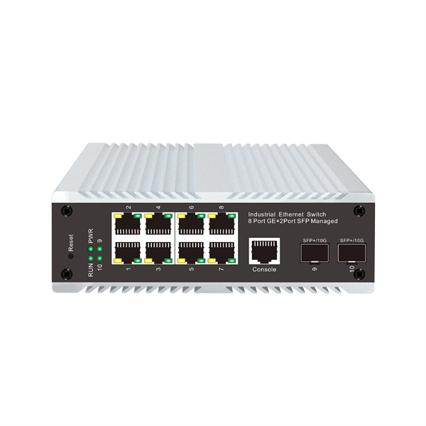
Which port on the switch is the optical interface
The optical port of an industrial Ethernet switch refers to the optical fiber interface, which has single-mode, multi-mode, gigabit, and gigabit specifications. Port types are limited to two: optical and Ethernet. RJ45 ports serve access-layer copper connections; SFP/SFP+ ports enable flexible 1G/10G uplinks; SFP28 delivers 25G for modern data centers; QSFP+ and QSFP28 support high-density 40G/100G spine–leaf. GBIC is an interface device that converts gigabit electrical signals into optical signals. This design enables end-to-end optical signal transmission, avoiding the conversion between electrical and. The optical ports on the switch are usually paired together, with one TX sender and one RX receiver. The. Most SFP fiber optic modules use LC connectors, while SC connectors are mainly found in legacy networks and MPO/MTP connectors are used for high-density cabling rather than directly on standard SFP modules. This connector landscape reflects how modern SFP deployments prioritize port density and.
[PDF Version]
-
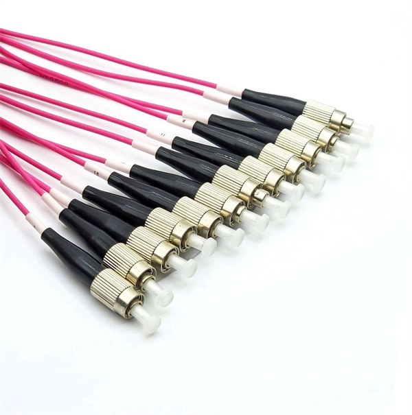
Does the FC interface transmit optical or electrical signals
The FC-0 specification includes cables, connectors, and optical and electrical parameters for a variety of data rates. This connector landscape reflects how modern SFP deployments prioritize port density and. Physical Fibre Channel (FC) is a high-speed data transfer protocol providing in-order, lossless delivery of raw block data. Fibre Channel is primarily used to connect computer data storage to servers in storage area networks (SAN) in commercial data centers. Host Bus Adapter (HBA) An HBA is a dedicated hardware component that connects a server to a Fibre Channel storage. Traditionally, compute operating systems have communicated with peripheral devices over channel connections, such as Enterprise Systems Connection (ESCON) and SCSI. Channel technologies provide high levels of performance with low protocol overheads. The connector mechanically orients the fiber cores, allowing light to pass and travel through.
[PDF Version]
-
10 Gigabit Ethernet card optical module not connected to fiber optic cable
Troubleshooting SFP+ link issues in 10 GbE networks requires attention to module type, match of speed and wavelength, clean fiber connections, correct configuration, thermal management, and equipment compatibility. You can quickly resolve SFP+ Module connectivity issues by following a systematic optical transceivers troubleshooting process. Check for common connection problems, such as link failures or modules not recognized. Check compatibility between the optical module and switch Most switch brands have specific compatibility requirements. During network upgrades, many enterprise users encounter a common issue: after replacing 10G broadband lines or inserting 10G SFP+ optical modules, the switch still fails to operate at full 10G bandwidth or even fails to recognize the modules. We've listed the five most common ones. First of all, let's briefly recap what SFP and SFP+ stand for. SFPs – short for 'small form-factor pluggable' – are compact, hot-pluggable devices.
[PDF Version]
-
Switches are all 10 Gigabit optical
To implement different 10GbE physical layer standards, many interfaces consist of a standard socket into which different physical (PHY) layer modules may be plugged. PHY modules are not specified in an official standards body but by (MSAs) that can be negotiated more quickly. Relevant MSAs for 10GbE include (and related X2 and XPAK), and. When choosing a PHY.
-
Hazards of Laying Optical Cables
Optical fibers, though renowned for their efficiency and bandwidth, aren't immune to risk factors that could spawn safety hazards. The very nature of fiber optic cabling requires handling microscopic strands that, when damaged, can cause signal loss or, worse, physical harm. Understanding the safety hazards that go with fiber optic cable is critical for those who install or maintain fiber optic systems. As electrical professionals, most of us take fiber optic (FO) safety for granted. Recognizing the potential safety hazard inherent in the installation and maintenance of optical fibers is crucial to mitigating risks of personal or property damage. Know the standards that apply to your work Whether you're installing new fiber optic cables or troubleshooting and repairing an existing fiber network, a working knowledge of the regulations that apply to your. However, fiber optics installation is not without risks. Even the output of OTDRs, WDM and fiber amplifier systems, which are. Working with fiber optic cabling requires precision, skill, and a strong understanding of cabling safety.
[PDF Version]
-
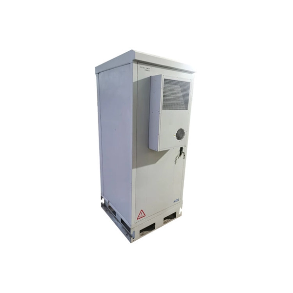
North Macedonia Optical Line Terminal 10G
The 10G SFP+ LR Ethernet Line optical transceiver transmits data over single mode fibre at a distance of up to 10km. The transceiver operates on 1 wavelength and works in point-to-point scenario. Modern OLTs offer communication service providers (CSP) the ability to launch multigigabit services to tens of thousands of subscribers from a single location or just ten. Fiber-to-the-home. HA7308VX is a small capacity 8 port OLT device launched by HiOSO. It can be used with HA7200 series ONU and passive optical distribution network (ODN) to form a passive optical network to achieve performance management, fault management, and configuration management of the equipment. 5G/5G/10GBase-T Multi-rate SFP+ Module (Twisted Pair Category Cable, 100m 1G/2. 5G Cat5e, 70m 5G Cat5e, 30m 10G Cat6a/7, RJ-45, C-temp) Specifications Form. Field-proven EPON and 10G-EPON OLT SoC solutions Cortina family of Optical Line Terminal (OLT) SoCs completes the end-to-end solutions for EPON and 10G-EPON applications.
[PDF Version]