-
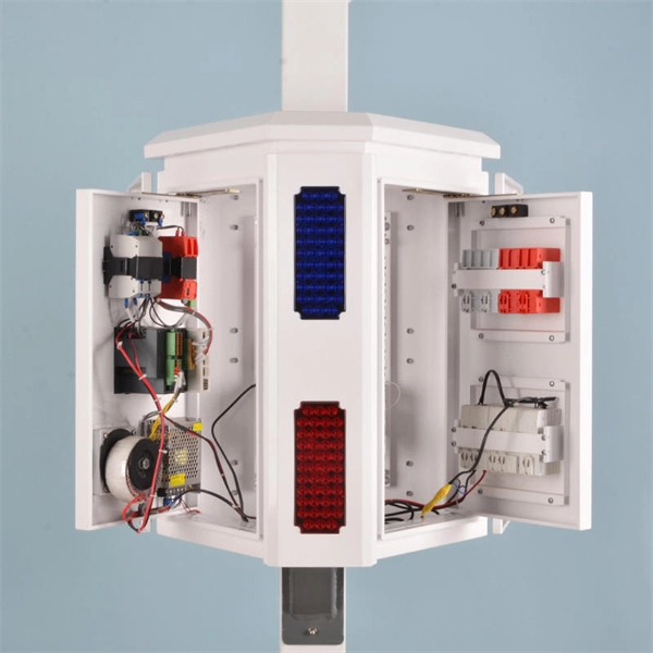
Distribution Box Ground Resistance Test
The selective testing method uses one clamp and two stakes. It allows you to measure the ground resistance at specific parts of an installation, isolating the system to check or reference what's in place. Th.
-
Multimode optical cable test length requirements
The cable should be longer than either of the following specifications, Event Dead Zone or Loss Dead Zone and the pulse length being used. Corning recommends that all fiber optic systems be tested to a minimum set of standards. So, you drop everything and i vestigate. He's right – it is n t working. Link testing of multimode segments should be done with an 850/1300nm dual wavelength unit. Since there is not an IEC/EIA. The length of launch cable used can very depending on the measurement needs. NEIS® are intended to be referenced in contrac documents for electrical construction ation or liability to users of this publication. Existence of a standard shall not preclude any member or nonmember of NECA or FOA from specifying or using. Other than for short-reach single-mode applications that are more susceptible to reflections and take connector reflectance into consideration, insertion loss testing, length, and polarity are really all you need for Tier 1 certification testing. Measured in decibels (dB), insertion loss is the. ANSI/TIA‑568.
[PDF Version]
-
How to test the continuity of a multimode fiber optic cable
The three standard methods for testing fiber optic cabling are a visible light source, power meter and light source, and optical time domain reflectometer (OTDR). Fiber optic testing for continuity is crucial in ensuring that light transmits through fiber optic cables without interruptions, safeguarding seamless data transmission. As the components like fiber, connectors, splices, LED or laser sources, detectors and receivers are being developed, testing confirms their performance specifications and helps. Fiber optic testing ensures the performance and reliability of fiber optic networks. It helps minimize downtime, reduce maintenance costs, and support system upgrades or reconfigurations. If it's a long outside plant cable with intermediate splices, you will probably want to verify the individual splices with an OTDR also, since that's the only way to make.
[PDF Version]
-
Latest Standards for Relay Protection Withstand Voltage Test
IEC 60255-5 is the standard that defines insulation coordination for these devices — the test voltages, impulse withstand levels, and minimum insulation resistance values that every protection relay must meet. This article breaks down the standard's requirements with the specific clause numbers and. Abstract: Design tests for relays and relay systems that relate to the immunity of this equipment to radiated electromagnetic interference from transceivers are specified in this standard. Two types of tests are specified: the oscillatory (SWC) and. IEEE Standard for Relays, Relay Systems, and Control Devices used for Protection and Control of Electric Power Apparatus--Surge Withstand Capability (SWC) and Electrical Fast Transient (EFT) Requirements and Tests Abstract: Design tests for relays, relay systems, and control devices used for.
[PDF Version]
-
How to connect the fiber optic test patch cord
Just use the one-jumper reference method to set the reference and an adapter to connect the jumper to the test reference cord. You can put in a fibre patch cord at home. You just need to follow easy steps and be careful. Unfortunately, equipment cords are also. Correct patch-cord installation is essential for maintaining low insertion loss, stable return loss, and long-term reliability in both indoor and outdoor fiber networks. This guide addresses expert-certified best practices applied by professionals in the telecommunications, data. Watch as we demonstrate the testing process for 12-fiber MPO patch cords using a laser source. more Watch. In today's high-performance networks, fiber optic patch cables are the lifelines that ensure smooth data flow across switches, servers, and routers. Even the most advanced optical transceivers can only perform at their peak when paired with properly installed, clean, and precisely managed fiber.
[PDF Version]
-

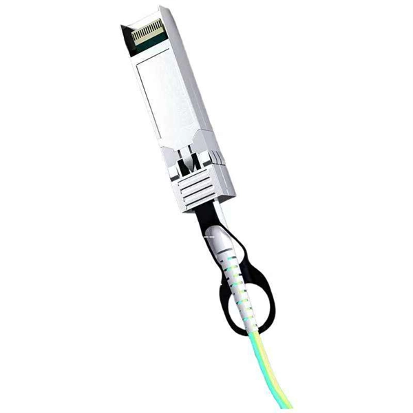
Optical module test power not adjusted too low
What does it mean if the transmitted power is too low? Low transmitted power can mean the connectors are dirty. Clean the connectors, check the module, and look at the fiber. If it still does not. Stable optical power is the foundation of every high-capacity optical transport system. Even minor deviations—whether too high, too low, or unstable—can impact signal integrity, trigger service alarms, or interrupt traffic on DWDM, OTN, or long-haul optical line systems. Because optical networks. The article Digital Diagnostic Function (DDM) For Optical Modules describes that DDM function can be used for real-time monitoring and fault location of the module's working status, in which the optical module's transmitting optical power and receiving optical power are the key parameters for. To test transmitted power in sfp optical modules, you use an optical power meter to get exact results. Many sfp modules also have DOM/DDM, which lets you see digital diagnostic monitoring data on network equipment. Built into modern SFP/SFP+/ SFP28 /QSFP family modules and standardized by SFF-8472, DDM/DOM exposes real-time values for the module's temperature, supply.
[PDF Version]
-
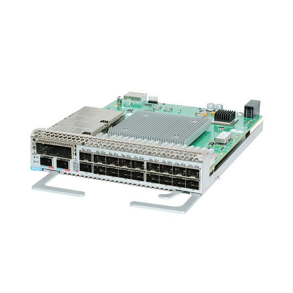
How does the optical module test group perform its tests
Optical modules will go through strict testing and quality inspection procedures before shipment, such as material testing, parameter testing, aging testing, real machine testing, end-face testing, etc. In fiber optic networks, optical transceivers such as SFP, SFP+, QSFP28, and QSFP-DD play a vital role in converting electrical signals into optical signals and vice versa. Testing these modules ensures performance, compatibility, and long-term reliability in bandwidth-intensive environments like. QSFPTEK suppliers have strict transceiver testing and quality control processes, and each optical module is delivered with a complete testing process. Optical modules can realize end-to-end signal transmission, and it performs optical communication through optical fibers. However, due to the architectural differences between 4-channel and.
[PDF Version]
-
Fiber optic cable test chart to check for broken ends
Use a Fiber Inspection Microscope – 200–400× magnification reveals scratches or pits on ferrule end-face. Visual Fault Locator (VFL) – Injects a red laser (650 nm); light leakage indicates bend, crack, or break. The process of testing any fiber optic cable plant during and after installation includes all the procedures covered so far. As network speeds and bandwidth demands increase, fiber performance requirements have become more stringent. Corning recommends that all fiber optic systems be tested to a minimum set. Here are the most common fiber optic testing methods used by network professionals: Conducting a visual inspection test involves using a fiber scope or microscope to examine the endfaces of connectors for dirt, scratches, or cracks. Cable contamination can also.
-
Fireproof cable tray fire resistance duration
20 min that does not exceed 150 m2, and a peak smoke release rate that does not exceed 0. 3 ft2/sec) when tested using the FT4/IEEE 1202 flame test in either UL 1685 or UL 2556. Focuses on fire resistance, including burn duration and flame spread. Measures smoke, acid gas, and toxic gas emissions. International standard defining general fire performance requirements for cable trays. If your cable trays don't meet these standards, they could fail when exposed to fire. Must be listed as having adequate fire resistance and low-smoke producing characteristics by exhibiting a. The UL 1257 testing standard evaluates the performance of cable tray and conduit assemblies in a fire environment by subjecting them to various temperature conditions. Core Fire-Resistant Layer: The inner layer is wrapped with. Where cables pass through shafts, walls, slabs, or enter electrical panels or cabinets, openings shall be tightly sealed with firestopping materials in accordance with design requirements.
[PDF Version]