-

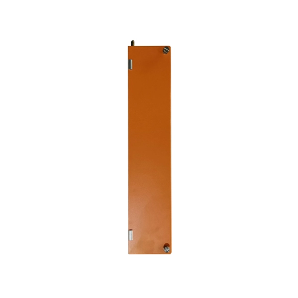
What does a 72-core optical cable look like
GYTA53 fiber cable consists of 250um fibers held in gel-filled PBT loose tubes, and wrapped around a phosphatized steel wire central strength member. A waterproof compound fills the loose tube, and the center of the cable core is a metal reinforced core. 72 core fiber optic cable should be selected by fiber standard, cable structure, jacket, tensile strength, installation route, drum length, testing, and quantity. single mode GYTA53 fiber optic cable and multimode. Fibertronics' Fiber Optic Distribution Cable is composed of high quality colored tight buffers, aramid yarn and a PVC outer jacket. Their small bend radius allows for fast installations and easy terminations within confined. Corning ribbon plenum cables are designed for use in plenum, riser and general purpose environments for intrabuilding backbone installations and for high-fiber-count data centers.
[PDF Version]
-
Optical cable channels are divided into
The light signal is divided into multiple channels with different frequencies and wavelengths, each transmitting a different data stream. In general, the fiber cable link system will be more secure if the fewer fiber cable segments. This region occupies a bandwidth of 95nm or 11THz! 8 cn cor where L is the fiber length, c is the speed of light, and ncor and nclad are the core and cladding refracitve indexes, respectively. Why not always use SMF? Optical phase information is lost in the detection process. What is a wavelength? What are optical wavelengths? What are nominal. In telecommunications, frequency-division multiplexing (FDM) is a technique by which the total bandwidth available in a communication medium is divided into a series of non-overlapping frequency bands, each of which is used to carry a separate signal. It essentially consists of a data transmitter, a transmission fiber (in some cases with built-in fiber amplifiers), and.
[PDF Version]
-

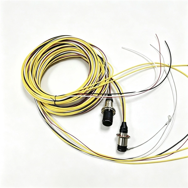
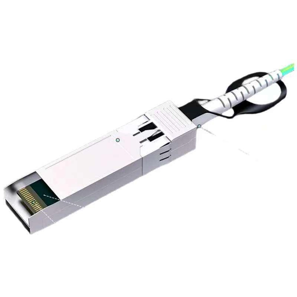
Single-mode port connected to multimode fiber optic cable
Single mode and multimode fiber cables are quite different when it comes to size, light source, signal, and so on. So, they definitely are not interchangeable, and compatibility issues can occur when you try to connect a single mode fiber optic connector to a multimode network. This is where fiber conversion comes in. Single-mode. To realize the short-range direct connection to the end B switch with the same port, the same 10GBASE-SR SFP+ module should be plugged into the end B switch port. What if end B is located in. It's possible because Multi-mode optical cables have a very wide fiber core – 62. Understanding the key differences between these two technologies is essential for IT professionals, business owners, and even homeowners looking to future-proof their network.
-
Translate the cable tray by 45 degrees
To create a 45-degree bend, cut the side rails to remove a segment calculated by the formula (Tan (22. Google's service, offered free of charge, instantly translates words, phrases, and web pages between English and over 100 other languages. So basically from my middle line what size to mark either side to cut my lip away to create different angles. Calculate horizontal, vertical, or compound cable tray offsets based on bend angle, offset distance, and available installation space. Measure this distance along the straight tray. ADVANCED S PRODUCTS I ASP 45° inuous system as well as stand-alone elements. 5∘ cuts on two separate pieces of cable tray. The second piece's cut must be in the opposite direction. Easy step to make 45 degree offset cable tray/Pipe and Air duct Cable tray 90 Degree Bend ! Cable tray ( Hindi) Cable tray 22. Distance of 145 mm ×.
[PDF Version]
-
Installation of galvanized plastic cable trays
This guide covers the critical steps, from selecting the right electrical cable tray and performing accurate cable fill calculations to managing a safe cable pull through and ensuring all bonding and grounding requirements are met. Are you looking for a cost-effective and durable solution for organizing and protecting your cables? Look no further than cable tray galvanized. But before you lay the first tray or clamp down a single cable, you need a solid plan. This guide breaks down the process step by step. The selection of material and finish is a function of the environment in wh tant in a wide range of environments, and easily formable (Appendices II and III). The process described here takes a systematic approach to ensuring that cable tray installations meet safety, reliability, and project-specific needs while following to. Method Statement installation of Cable Trays and Ladders - Planning Engineer FZE.
[PDF Version]
-
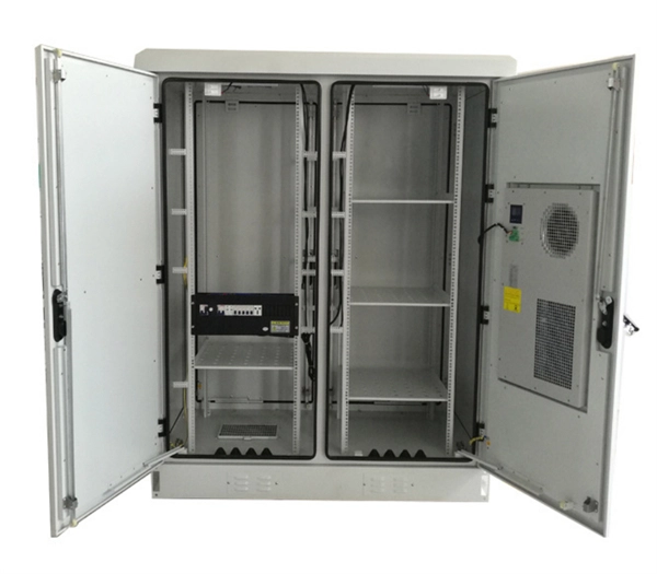
Is installing cable trays complicated
Installing a cable tray system requires careful planning to ensure it can support the weight of the cables and adheres to electrical safety codes. Here is a step-by-step guide on how to install a standard metal cable tray system (e., ladder or perforated type). This guide covers the critical steps, from selecting the right electrical cable tray and performing accurate cable fill. Proper installation of cable trays is important to ensure hassle-free cable management. The key requirements for cable tray installation include: Incorrect installation can lead to overheating, cable damage, or system failure. This is why proper planning and execution are. Hubbell's NEXTFRAME® Ladder Tray is the effective and widely used cable runway that supports and delivers bundles of cable between cabinets, racks, and closets, along walls, and suspended from ceilings. The Ladder Tray features light, rugged, tubular steel construction. The beginning of success is to review the Bill of Quantities (BOQ) so that.
[PDF Version]
-

Bangladesh finished optical cable
Find single-mode, multi-mode, and armored fiber cables for FTTH, data centers, and backbone networks. Shop with confidence at Smart View BD for the best price in Bangladesh with genuine products and official warranty. Is A Leading Manufacturing Industry Of Optical Fiber Cables (OFC) Of The Country With Fourth Generation German Technology Machineries. Order online to get delivery in BD. Our factory is located at Plot-10, Block-04, kaliakoir Hi-Tech park Industrial Estate which is at the heart of the Gazipur City Corporation.
-
How to pull up a power fiber optic cable
Fiber optic cables should always be pulled by the strengthened yarn fibers inside the outer jacket. This article explores recommendations for pulling and installing fiber optic cable. Most fiber optic cables boast a pull strength of 100 – 200. Fiber optic cable is surprisingly strong, durable and pliable; however, several best practices should be followed to ensure a successful cable installation. Most fiber damage does not come from normal operation after the system is live. More than half of cable problems happen because of wrong pulling. In 2025, new tools like hydraulic blowers, smart monitors, and better grips help you lower risks, save money, and keep the. A duct is available from point A to point B, a pull tape is blown in, a fiber optic cable is attached to it and the cable is pulled through the duct.
-

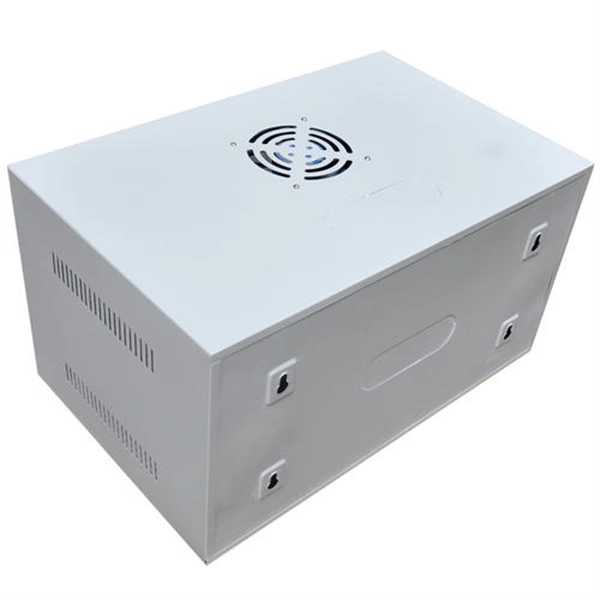
Benin Optical Cable Blowing Machine
A cable blowing machine (also known as a fiber blowing machine) is a machine designed to fit cables into telecommunication ducts and with the use of compressed air or water.
-
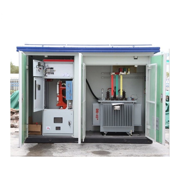
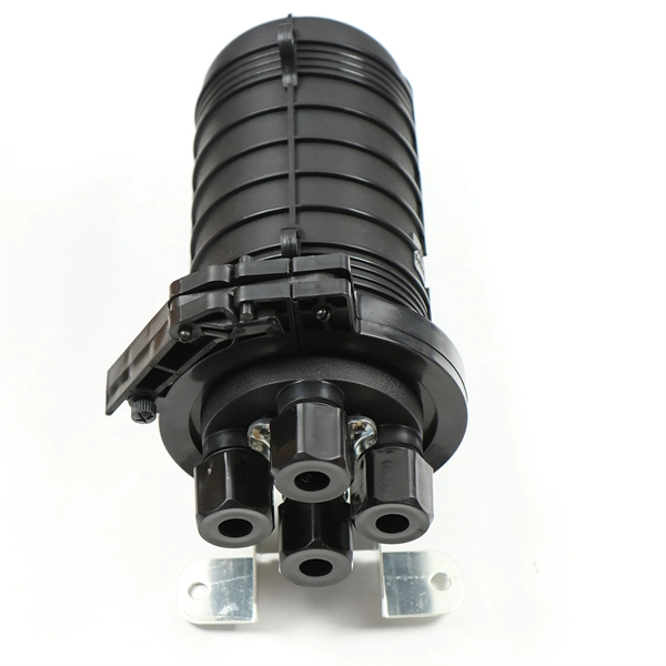
OPGW optical cable manufacturer in Lebanon
APAR designs and manufactures OPGW cables using advanced stranding technology, precision fiber integration processes, and stringent quality control systems. is a leading telecommunication company and a leading provider of telephony systems, networking, security and CCTV systems, Home Automation Systems, and Nurse Call System. IMATEL was founded in 1986 as a telecommunication provider. OptiLink was built on a simple belief: world-class fiber infrastructure shouldn't be reserved for the largest enterprises. This comprehensive analysis profiles the Top 10. Optical fiber composite overhead ground wire (OPGW) 1. Installed at the top of high-voltage and extra-high-voltage transmission lines, OPGW cables provide lightning. OPGW is primarily used by the electric utility industry, placed in the secure topmost position of the transmission line where it “shields” the all-important conductors from lightning while providing a telecommunications path for internal as well as third party communications.
[PDF Version]
-
Requirements for installing cable trays on highways
Cable tray systems are recognized as a wiring method by many national and international electrical codes. Typical requirements address: Tray construction, load ratings, and materials. Support spacing, mechanical strength, and. Article Summary: A compliant cable tray installation requires a thorough understanding of NEC Article 392, proper structural support, and precise installation techniques. This guide covers the critical steps, from selecting the right electrical cable tray and performing accurate cable fill. This article explains the main requirements and good practices for cable tray systems, including tray types, materials, loading, supports, bonding, cable selection, and installation details.
-
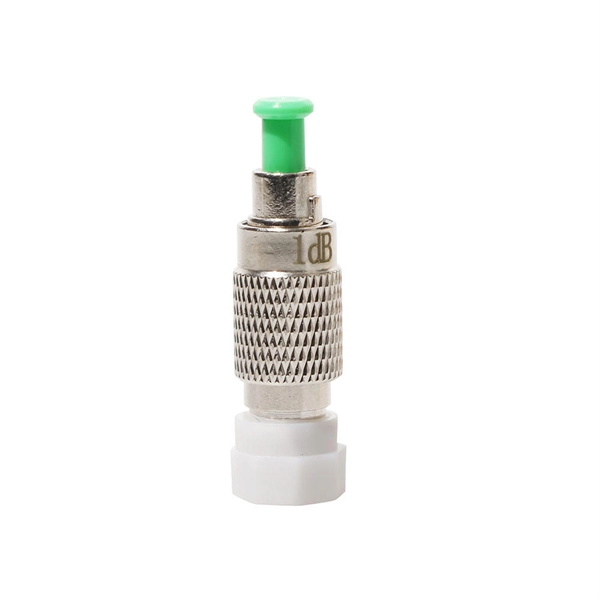
Fiber optic cable splice cannot be pulled out
This is often due to issues with connectors, splices, or faulty equipment. Use an OTDR to identify points of high return loss or reflection events along the link. Check the fiber's end-faces for imperfections and re-polish. A single imperfect splice can disrupt connectivity for businesses, schools, and homes, causing slow speeds, intermittent outages, and costly downtime. Whether it's from misalignment, dust contamination, environmental stress, or poor splice protection, these problems can quickly escalate if not. Successful splicing or termination relies on first being able to expose the fibers completely and safely. If the installer cannot do this, splicing or termination is irrelevant. This wikiHow article will teach you how to splice a cut fiber optic cable back together with a fiber optic stripper and cutter and a fiber optic crimper.
[PDF Version]