-
The single-mode fiber optic distance is 300 meters
A: For most applications, the maximum distance of a single-mode cable is around 160 kilometers. Q: How far can multimode fiber go? A: It varies with the data speed and fiber type. Due to the small core, only one optical mode is allowed to be transmitted. This characteristic enables single-mode fibers to transmit signals over long distances with low mode dispersion (mode. Fiber optic cable can be run anywhere from 300 meters up to 80 kilometers (roughly 50 miles) depending on the cable type, transceiver used, and network standard. Simply plug the cable to any fiber port on the device and high speed fiber optic link between two long distance locations can be generated by. Single-mode fiber (SMF): Uses a single light path, enabling it to transmit data over longer distances with less signal loss.
-
Incident Power in Fiber Optic Communication
The incident optical power is used to suppress nonlinear effects and ensure transmission quality. In the following figure, optical power at point C is the incident optical power. Why Do We Need Incident Optical Power? The transmission performance of a WDM system is affected by the. This AE Note explains the differences between Optical Return Loss (ORL) and Back Reflectance in fiber optic systems. Even minor deviations—whether too high, too low, or unstable—can impact signal integrity, trigger service alarms, or interrupt traffic on DWDM, OTN, or long-haul optical line systems.
-
How many meters long is the indoor fiber optic cable approximately
Fiber optic cable can be run anywhere from 300 meters up to 80 kilometers (roughly 50 miles) depending on the cable type, transceiver used, and network standard. For most enterprise or data center applications using multimode fiber, the practical limit sits between 300 m and 550 m. There are three main reasons for this: First, high-bandwidth signals are more susceptible to chromatic dispersion than. The maximum distance for single mode fiber optic cable can extend up to several hundred kilometers, making it ideal for long distance data transmission. 652,” which is commonly used in telecommunications networks. Range tells you how much ground you can cover before needing tools like optic cable extender devices or extra cables. Multimode fiber comes in OM1 (legacy), OM3, OM4, and OM5 (OM2 is obsolete) and supports much shorter distances. These two types require different electronic equipment.
[PDF Version]
-
How to route fiber optic cables for high-voltage power lines
This technique takes a small, lightweight fiber optic cable and wraps it around or lashes it to the power line. The cable is called optical power attached cable (OPAC), and it is lashed to the power cable with a specialized tool that is pulled from the ground, such as a. Installing ADSS (All-Dielectric Self-Supporting) cables near live power lines demands precision, compliance with safety standards, and an understanding of high-voltage risks. This guide from GL FIBER breaks down the process into actionable steps, aligned with IEEE 524 and IEC 61935-1 protocols, to. Most aerial fiber optic cables are installed by lashing to a steel messenger wire strung between poles, but there is a category of cables with special high-strength jacket designs called all-dielectric self-supporting (ADSS) cables. ADSS cables are designed to withstand very high-tension loads. bles in a high voltage environment, with typical line voltages of 115 kV or more, requires the evaluation of certain critical parameters. Curr ntly, there are a limited number of industry documents that address the requirements for optical fiber cables near high voltage circuits.
[PDF Version]
-
How to pull up a power fiber optic cable
Fiber optic cables should always be pulled by the strengthened yarn fibers inside the outer jacket. This article explores recommendations for pulling and installing fiber optic cable. Most fiber optic cables boast a pull strength of 100 – 200. Fiber optic cable is surprisingly strong, durable and pliable; however, several best practices should be followed to ensure a successful cable installation. Most fiber damage does not come from normal operation after the system is live. More than half of cable problems happen because of wrong pulling. In 2025, new tools like hydraulic blowers, smart monitors, and better grips help you lower risks, save money, and keep the. A duct is available from point A to point B, a pull tape is blown in, a fiber optic cable is attached to it and the cable is pulled through the duct.
-
What type of fiber optic cable is used for power transmission towers
Optical Ground Wire (OPGW) cable is a type of fiber optic cable that is specifically designed for use in overhead power transmission lines. These cables are made up of extremely thin strands of glass or plastic, known as optical fibers, which are encased in protective sheathing. The fibers are arranged in. Besides the use of special cables on transmission and distribution towers or poles, the installation of fiber optic cables for utilities may require the shutdown of electrical distribution for installation, although some installations are possible without shutdown. Such cable combines the functions of grounding and telecommunications. The all-dielectric design eliminates.
-
Fiber optic cable shows fault pigtail broken but there is still network connection
“To troubleshoot fiber network issues, start by inspecting physical connections, testing signal strength, and verifying device functionality. Use OTDR for advanced diagnostics and resolve configuration errors to restore performance. ” External Links · Fiber Optic Standards. Fiber optic networks are celebrated for their speed and reliability, but even the best systems can encounter problems. When issues like signal loss, slow speeds, or intermittent connectivity arise, systematic troubleshooting is key. Knowing how to recognize and diagnose these problems quickly ensures. In the high-stakes world of optical networking, even a minor disruption in a Pigtail Fiber connection can cascade into costly downtime, affecting data centers, telecom services, or industrial systems. This article equips engineers and network operators with actionable strategies to diagnose. Physical faults are obvious when you can locate the jacket damage; less obvious when a cable is pinched in a door or crushed under weight. Short accessible runs often show the fault with a Visual Fault Locator (VFL), which uses visible red light to reveal breaks or tight bends; for buried or long.
[PDF Version]
-
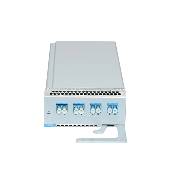
The Role of Fiber Optic Communication Power Module
The optical module serves as a crucial component in optical fiber communication systems, operating at the physical layer, which is the lowest layer in the OSI model. Its primary function is to achieve optoelectronic conversion by converting electrical signals into optical. The working principle of optical modules is illustrated in the diagram shown in the Optical Module Working Principle Diagram. An. That is, metal medium communication represented by coaxial cables and network cables is gradually being replaced by optical fiber media. As IoT and AI continue to expand, the need for faster optical transceivers.
-
Is a network cable considered a power cable or a fiber optic cable
Networking cables refer to cable technologies such as fibre-optic and coaxial cable that are used to transmit data between computers, routers, switches, servers, and other forms of network-enabled devices. Different types of network cables, such as coaxial cable, optical fiber cable, and twisted pair cables. There are different types of both, offering different features and they're designed with different use cases in mind, so doing a direct fiber optic cables vs. Ethernet cables comparison isn't the whole story. In this blog, we will examine what networking cables are, how they can be used, the various types of networking cables, and how to determine. What are the different types of network cables? The main types of network cables are coax, fiber optics, and shielded and unshielded twisted pair. As enterprises deploy new technologies, it's critical to select the right cables. Each is different and suitable for different applications.
[PDF Version]
-
Is fiber optic temperature measurement single-mode
Distributed fiber-optic temperature sensors can be realized with ordinary single-mode fibers, not containing any special structures such as fiber Bragg gratings. In many cases, one uses telecom fibers, operated in the 1. Our company has independently developed the DTS-BLY-5S (SMV), which features low power consumption of as low as 6W, a three-proof motherboard (anti-fungus, moisture-proof, and salt spray-proof), a temperature sensing distance of over 24 km, a maximum of 16 channels, compatibility with fiber cables. Optical temperature sensors are temperature sensors which are based on optical technology — in most cases, on fiber optics. Learn more about the ODISI for high-definition temperature measurement Strain sensors based on. In this paper, the self-phase modulation (SPM) effect in a double-cladding single-mode tellurite optical fiber (DC-SMTOF) was exploited for temperature sensing. Modes are the possible solutions of the Helmholtz equation for waves, which is obtained by combining. It is a single point contact temperature measurement system. The light source is used to excite the Fluorescent material.
[PDF Version]
-
Where should a gigabit router be plugged into a 500m fiber optic connection
Fiber optic modem (ONT): Most fiber connections require an Optical Network Terminal (ONT), provided by your ISP. Compatible router: Verify that your router supports fiber optic input (look for an SFP or WAN port labeled "ONT" or "Fiber"). This. The two most common types of Ethernet speeds are Fast Ethernet (10/100Mbps) and Gigabit Ethernet (10/100/1000Mbps), which are more than enough for most people's local network uses. But as the internet access increases, the network speed decreases gradually since Ethernet cannot handle such heavy. An experienced installer knows to use Ethernet switches to extend connections and with the advent of PoE powered switches this even negates the need for an AC electrical outlet to power up the remote switch. Else any of. This article breaks down scientifically validated rules for optimal router positioning, supported by engineering data, peer-reviewed studies, and practical deployment experience. A modern Wi-Fi router is capable of far greater performance than most households ever experience.
[PDF Version]