-
Fabrication of Fiber Optic Pigtails
This guide covers everything: what fiber optic pigtails are, how they differ from patch cords, which connector and polish type to specify, how to choose between mechanical and fusion splicing, and the real-world applications where pigtails are the right call. Get the wrong connector type, the wrong polish, or skip proper fusion splicing technique—and you're looking at elevated signal loss, increased back reflection, and a. This technology aligns fiber pigtail arrays for coherently combining different optical beams, reducing deviation in virtual beam waist position among endcapped fibers. Pigtails are fiber optic cables which are only terminated on one end. The success of a network in fiber optic cable installation heavily. Our Fiber Optic Patch Cord Production Line equipment includes everything needed to manufacture high-quality patch cables and pigtails: from cable making machines and pneumatic crimpers to precision polishing fixtures and IL/RL test stations. The connector end can be linked directly to network equipment, while the exposed end can be spliced to another fiber optic cable.
[PDF Version]
-
Fiber optic pigtails Network and carrier grade
In this comprehensive guide, we will explore the different types of fiber optic pigtails, including LC, ST, and SC pigtails. Each type has its own unique design, size, and compatibility features. 5m to 2m—that has a factory-terminated connector on one end and bare fiber on the other end. The bare fiber end. A pigtail fiber indicates a short length of optical fiber cable that has a pigtail connector (for example, SC, FC, ST, LC, etc. Get the wrong connector type, the wrong polish, or skip proper fusion splicing technique—and you're looking at elevated signal loss, increased back reflection, and a. IDEAL FOR CATV, FTTH/FTTX, TELECOMMUNICATION NETWORKS, DATA PROCESSING NETWORKS, LAN/WAN NETWORKS.
-

Laying pigtails and installing fiber optic patch cords
This guide covers everything: what fiber optic pigtails are, how they differ from patch cords, which connector and polish type to specify, how to choose between mechanical and fusion splicing, and the real-world applications where pigtails are the right call. Today, I'll show you how to pick the right patch cord or pigtail — step by step. A Fiber Patch cord connects two devices. It's ready to use out of the box. Mixing them up drives costs higher, increases loss, and slows your rollout. Remove the outer coating carefully to expose the fiber. Align and fuse the pigtail fiber with the main. In this detailed video, we'll walk you through the fiber optic pigtail splicing process — from preparation to final testing. If you're new to fiber optics or want to enhance your technical skills, this guide will help you understand how to splice fiber pigtails safely and efficiently.
[PDF Version]
-
What do fiber optic pigtails connect to
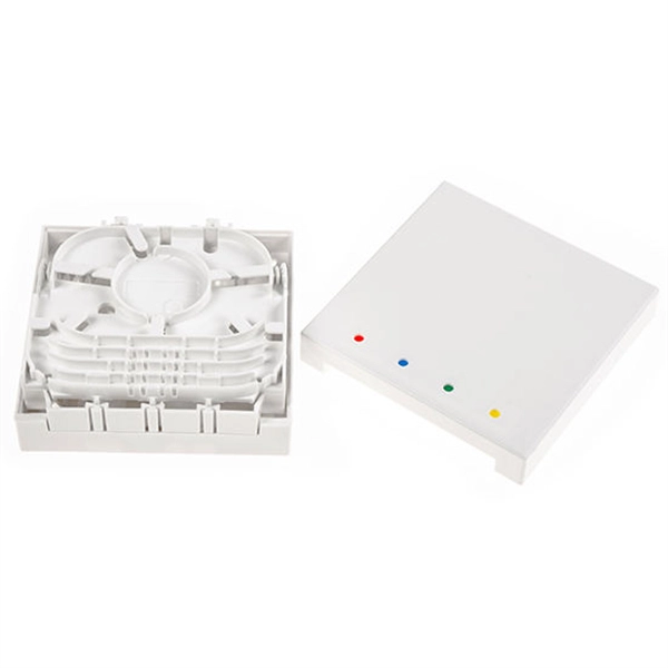
A fiber optic pigtail is a short optical fiber cable that has a connector on one end and an exposed (unterminated) fiber on the other. The connector end plugs into devices like transceivers or patch panels, while the bare end is typically fusion spliced to a fiber optic cable. They are the bridge between fiber optic cables in the field and the equipment or patch panels that manage them. By combining factory-installed connectors with spliced bare fiber, pigtails ensure that network installers can create fast, reliable, and cost-effective terminations.
-
Fiber Optic Cable Signal Tester
Fluke Networks is a market leader in enterprise fiber testing equipment, with a wide range of field-tough fiber testers to help you inspect, clean, verify, certify, and troubleshoot your fiber optic cable networks.
-

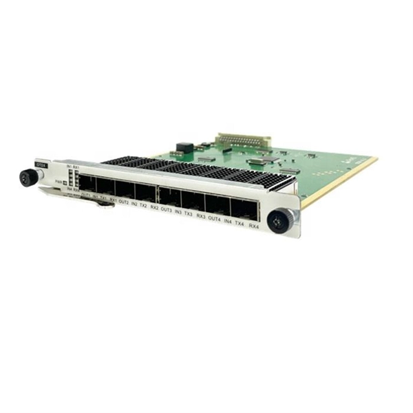
Single-mode port connected to multimode fiber optic cable
Single mode and multimode fiber cables are quite different when it comes to size, light source, signal, and so on. So, they definitely are not interchangeable, and compatibility issues can occur when you try to connect a single mode fiber optic connector to a multimode network. This is where fiber conversion comes in. Single-mode. To realize the short-range direct connection to the end B switch with the same port, the same 10GBASE-SR SFP+ module should be plugged into the end B switch port. What if end B is located in. It's possible because Multi-mode optical cables have a very wide fiber core – 62. Understanding the key differences between these two technologies is essential for IT professionals, business owners, and even homeowners looking to future-proof their network.
-
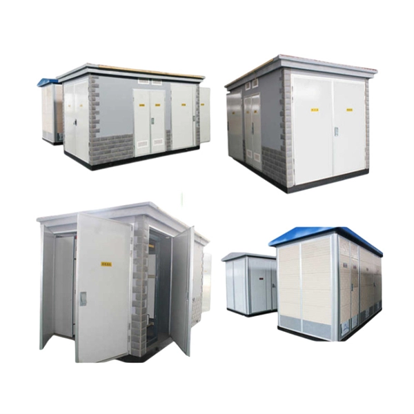
How to route fiber optic cables for high-voltage power lines
This technique takes a small, lightweight fiber optic cable and wraps it around or lashes it to the power line. The cable is called optical power attached cable (OPAC), and it is lashed to the power cable with a specialized tool that is pulled from the ground, such as a. Installing ADSS (All-Dielectric Self-Supporting) cables near live power lines demands precision, compliance with safety standards, and an understanding of high-voltage risks. This guide from GL FIBER breaks down the process into actionable steps, aligned with IEEE 524 and IEC 61935-1 protocols, to. Most aerial fiber optic cables are installed by lashing to a steel messenger wire strung between poles, but there is a category of cables with special high-strength jacket designs called all-dielectric self-supporting (ADSS) cables. ADSS cables are designed to withstand very high-tension loads. bles in a high voltage environment, with typical line voltages of 115 kV or more, requires the evaluation of certain critical parameters. Curr ntly, there are a limited number of industry documents that address the requirements for optical fiber cables near high voltage circuits.
[PDF Version]
-
Fiber Optic Channel Sharing
The goal of Fibre Channel is to create a storage area network (SAN) to connect servers to storage. The SAN is a dedicated network that enables multiple servers to access data from one or more storage devices. Enterprise storage uses the SAN to backup to secondary storage devices including disk arrays, tape libraries, and other backup while the storage is still accessible to the server. Servers ma. OverviewFibre Channel (FC) is a high-speed data transfer protocol providing in-order, lossless delivery of raw block data. Fibre Channel is primarily used to connect to in (SAN) in co. When the technology was originally devised, it ran over optical fiber cables only and, as such, was called "Fiber Channel". Later, the ability to run over copper cabling was added to the specification. In order to avoid confu.
-
AI-powered Fiber Optic Cable Maintenance
By integrating Fiber Optic Internet with AI-powered predictive maintenance tools, organizations can monitor their equipment in real-time and anticipate potential failures before they occur. To keep up with this rapid growth, the integration of cutting-edge technologies like Artificial Intelligence (AI) and Machine Learning (ML) is essential for optimizing. This article explores how AI's exponential growth is creating transformative demands on fiber optic cables, connectivity solutions, and the broader communications industry, and what innovative approaches manufacturers must adopt to meet these challenges. Machine learning models can adapt their behavior to changing network conditions, traffic patterns.
-
Principle of Fiber Optic Communication Spectrum Analyzer
These instruments are used to measure wavelength emissions from Lasers, Laser Diodes and LED's into the near infrared. From detecting signal distortions to optimizing optical. Optical spectrum analyzers are specialized instruments that measure light intensity as a function of wavelength. The COSA-4055 module offers the functionality and speed of an OSA in a handheld form factor at a fraction of. E/O converters use light-emitting elements such as semiconductor lasers, O/E converters use light-receiving elements such as photodiodes, and optical elements such as lenses are used at the input and output of optical fiber.