-

How to configure fiber optic patch panels in a computer room
Our guide delivers actionable, step-by-step best practices for rack layout, cable management, and patch panel installation. Following these steps helps you build a clean and efficient structured cabling system that simplifies maintenance and maximizes network performance. How to Install Fiber Optic Patch Panel Only by taking the proper steps can achieve a reliable network. A successful project begins with careful planning. Before a single cable is. In modern data centers, where high-speed and high-density connectivity is critical, organizing fiber optic patch panels effectively is essential for performance, scalability, and maintenance. Here's a step-by-step guide to help you properly arrange fiber optic patch panels in a data center. In this section, the common steps for connecting patch panels with fiber optic cables or network switches will be demonstrated.
[PDF Version]
-

Requirements for installing fiber optic cable poles
Comply with National Electrical Code requirements for cable ratings and fire safety. Prepare cable ends by sealing gel-filled cables and protecting buffer tubes to prevent water ingress and physical damage. You must follow strict installation guidelines for outdoor fiber optic. The Fiber Optic Association, Inc. (FOA) was founded in 1995 to help develop the workforce to build the fiber optic networks to support a rapid expansion in communications and the Internet. FO-VC2 JOINT USE - VERICAL MIDSPAN CLEARANCES 48. Since outside plant fiber optic networks can cover a broad range of installation types using varied components over different types of geography, it is impossible to. Let's discuss fiber optic installation requirements and best practices for a seamless installation. Engineers and. Some of the common tools include aerial storage for cables; telescoping poles; fiber heat shrink tube; brackets; blocks; cable saddles; fiber suspension clamp; cable rings, horizontal fiber splice closure, dome fiber splice closure, fusion splicers, etc.
[PDF Version]
-
Fiber Optic Passive Device Standards
IEC 61753-1:2018+A1:2020 provides guidance for the drafting of performance standards for all passive fibre optic products. There are a number of ways of finding out more about cabling standards. You can also get catalogs and/or visit the websites of a number of cabling. A passive optical network (PON) is a fiber-optic telecommunications network that uses only unpowered devices to carry signals, as opposed to electronic equipment. In practice, PONs are typically used for the last mile between Internet service providers (ISP) and their customers. 1x32 splits were common in North America for G-PON architectures. As XGS-PON continues to be adopted, some service. Fiber optics standards are published by SAE, IEEE and others and cover a variety of topics relating to the testing and construction of fiber optics cables in a variety of different applications ranging from military and industrial use. In essence, a PON is a fiber-optic system that delivers data from a single source to multiple endpoints using only.
[PDF Version]
-
ODF fiber optic sheath
An Optical Distribution Frame (ODF), also known as a fiber optic patch panel, is a specialized hardware unit that centralizes fiber optic cable connections. Acting as a “traffic hub” for light signals, an ODF: Organizes incoming and outgoing fiber cables. Whether in data centers, telecom central offices, or enterprise network rooms, ODFs enable efficient fiber management. In the intricate world of fiber optic networks, two pieces of hardware often sit side-by-side yet serve distinct, critical roles: the Fiber Patch Panel and the Optical Distribution Frame (ODF). While both are fundamental for connectivity and management, understanding their core differences is. Achieve successful cable management, handle high amounts of fiber cable and add density to fiber frames with the new DCX Optical Distribution Frame (ODF) System which features innovations like flippable cassettes, modular frame design and multiple configuration options. The ODF System Components. This complete guide explores everything you need to know about ODFs — from their structure, types, and key components, to installation best practices and modern design trends.
[PDF Version]
-
What are the uses of gigabit fiber optic patch cords
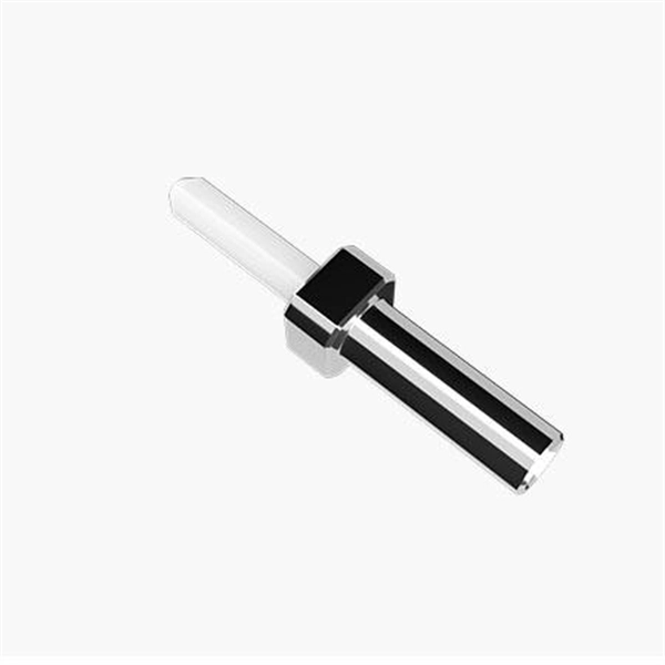
Fiber optic patch cables connect servers, switches, and storage systems with speed and precision. The yellow outer jacket makes them easy to distinguish. As data rates increase from 10G → 100G → 400G → 800G, patch cables must handle more bandwidth, more density, and stricter. Fiber optic patch cords, also known as fiber optic patch cables or fiber jumpers, are indispensable components in modern optical networks. Other types of fiber cable have different traits.
-
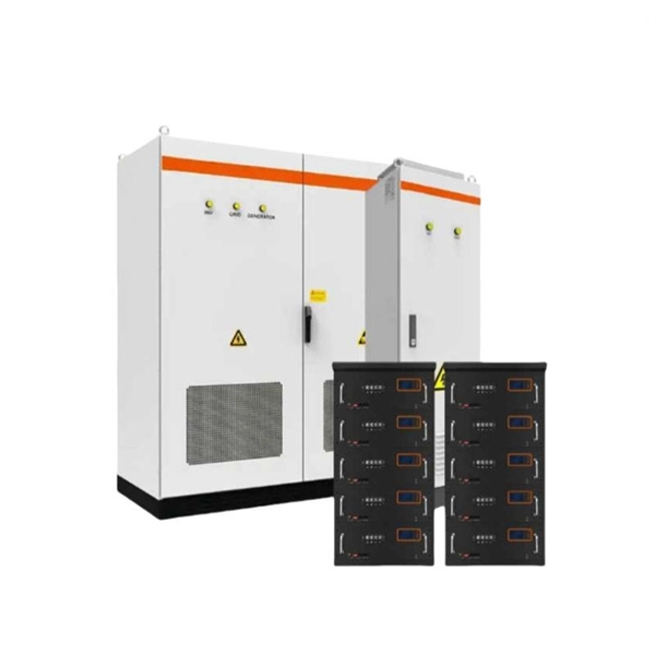
How to route fiber optic cables for high-voltage power lines
This technique takes a small, lightweight fiber optic cable and wraps it around or lashes it to the power line. The cable is called optical power attached cable (OPAC), and it is lashed to the power cable with a specialized tool that is pulled from the ground, such as a. Installing ADSS (All-Dielectric Self-Supporting) cables near live power lines demands precision, compliance with safety standards, and an understanding of high-voltage risks. This guide from GL FIBER breaks down the process into actionable steps, aligned with IEEE 524 and IEC 61935-1 protocols, to. Most aerial fiber optic cables are installed by lashing to a steel messenger wire strung between poles, but there is a category of cables with special high-strength jacket designs called all-dielectric self-supporting (ADSS) cables. ADSS cables are designed to withstand very high-tension loads. bles in a high voltage environment, with typical line voltages of 115 kV or more, requires the evaluation of certain critical parameters. Curr ntly, there are a limited number of industry documents that address the requirements for optical fiber cables near high voltage circuits.
[PDF Version]
-
Fiber optic cable does not support 1550
Multimode fiber is designed to operate at 850 and 1300 nm, while singlemode fiber is optimized for 1310 and 1550 nm. One of the major advantages of 1550 nm transmission is compatibility with Erbium-Doped Fiber Amplifiers (EDFA). All Singlemode fibers work very similarly in either wavelength—that is, you don't need to buy fiber based on wavelength, one fiber fits all. So, IF your cable assembly is built. This article delves into why 850, 1310, and 1550 nm are standard, what less-known regimes and tradeoffs exist, and how an OEM fiber-cable manufacturer can design and test with wavelength considerations built in. Consider the balance between attenuation and dispersion when designing your network for optimal performance.
-
Add fiber optic cable to the suspension line
Lashed (lashing to a separate messenger strand) — a fiber cable is lashed to a pre-installed suspension strand. Fiber optic cable suspension clamp installation manual made by Jera line. AFL's Mechanical Suspension installs easily while supporting vertical, transverse, longitudinal unbalanced loads and angle pulls without. Deploying fiber above ground on poles or towers removes the need for underground digging and is particularly useful when the ground is uneven, rocky or both. It is assumed that the reader is.
-
Extinction Ratio of Fiber Optic Sensors
In the world of fiber optics, the extinction ratio is a critical yet often overlooked parameter that can make or break signal integrity. This article explains what extinction ratio is, why it matters for reducing bit error rates in optical communication, and how it impacts optical module. Comprehensive Guide to Polarization Extinction Ratio in Fiber Optic Sensor s Introduction to Polarization Extinction Ratio The polarization extinction ratio (PER) is a critical parameter in fiber optic sensors that measures the degree of polarization extinction between two orthogonal polarization. Extinction ratio measurement at the connector level can quickly reveal alignment issues. The polarization axes of both fibers must be aligned before fusion. A poorly aligned splice is one of the most common sources of PER loss in. Cross coupling in regards to a birefringent fiber, quantified by extinction ratio, indicates the amount of light which is able to mix between the two polarization axes. To overcome this limitation, we propose and demonstrate a novel resonator design with an intrinsically high polarization.
[PDF Version]
-
How to use a 96-core fiber optic patch panel
These high-density fiber patch panels allow a mix-and-match of e2XHD fiber and copper snap-in cassettes - up to 96 LC fibers or 48 copper ports per RU. Cassettes quickly snap in and pull out of the panel, making installation and changes easier than ever. These individual strands will then connect to electronic devices. This is precisely the problem the MPO/MTP® patch panel was designed to solve. Frankly, if you're deploying 40G, 100G, or higher, you can't afford to ignore this technology. The 96 Core Slide Drawer Patch Panel 1U UHD MPO/MTP-LC 4 Cassette is a versatile solution for high-density fiber management in data centers and telecom networks. Designed for 19″ rack-mount cabinets, it accommodates up to four HD MPO/MTP-LC cassettes, providing a plug-and-play system that. OptoSpan's WM-96 Wall Mount Termination and Splicing Enclosures provide a convenient, secure and organized housing for fiber optic connections and terminations, as well as a central point for splicing fiber optic cables for indoor or outdoor installations.
[PDF Version]
-
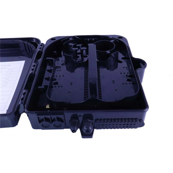
Is the fiber optic cable from the junction box considered a termination
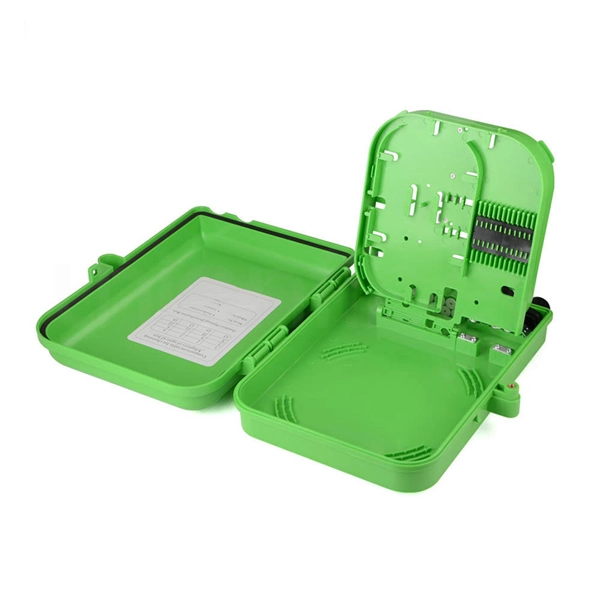
Optical fiber termination box: This serves as the termination point of a fiber optic cable. It essentially splits one fiber optic cable into individual fibers. Key Functions Typical Applications ZION FTB Highlights In essence: The Fiber Terminal Box is an end-user termination device for small-scale distribution. It functions as a junction between the incoming fiber cable and the outgoing customer-side fiber cable, where one fiber can be spliced, patched. A fiber connection box, also known as a fiber optic junction box, termination box, or distribution box, is a crucial component in fiber optic networks.
-
Manufacturing Process of White Fiber Optic Terminal Box
We show the manufacturing process of DIMI's Fiber Optic Terminal Box / FTTH Termination Box—from raw materials and injection molding to assembly, quality inspection, and packaging. If you're looking for a stable supplier for OEM/ODM and bulk orders, this video helps you understand our production. Minqing Fibramerica Technology, under its trade name FIBRAMÉRICA, is one of the world's leading companies dedicated to the design, development, manufacture, distribution and marketing of advanced optical connectivity solutions. It mainly used for indoor fiber optic cable straight through. Strictly selected quality fiber optic termination box in China for your FTTH & OSP networks, your procurement will be easy & cost-effective. You can ask us to. From mission-critical surveillance systems and telecommunications to enterprise data centers and Fiber-to-the-Home (FTTH) applications, optical fiber offers unparalleled speed and low signal attenuation over long distances. However, the very characteristics that make fiber optic cables.
[PDF Version]