-
Fiber Optic Fusion Splicer Calibration Time
Next the splicer prompts to confirm that a Quick Optimization or Arc Calibration has been performed before splicing the fiber. Fusion splicing is the process of fusing or welding two fibers together usually by an electric arc. The guide provides the complete workflow, covering safety precautions, tool selection, fiber preparation, fusion operation, quality control, and. Fusion splicers are essential for creating low-loss, high-performance fiber optic connections in telecom, FTTH, and data center applications. Top-rated models. It is recommended practice to keep fiber optic test equipment calibrated in measurement to ensure fast troubleshooting when locating network failures or when providing optical attenuation or optical cable length certification results. These records are required to close out a project and receive. At FiberOptic Resale our technicians have the experience and knowledge to clean and calibrate a broad range of fusion splicers and cleavers. Please follow all warnings and cautions for your safety and the protection of the equipment.
[PDF Version]
-
Does fiber optic extension require a fusion splice tray
The process requires a fusion splicer, a high-precision machine that aligns the fiber cores and controls the arc. Splicing fiber optic cable is an extremely important phase for making dependable, high-speed communication infrastructures. Regardless of the type of fiber network you're deploying, be it for telecom, enterprise data centers, or smart city infrastructure, fusion splicing provides the benefits of. Typically ships in 14 day (s) Actual lead time confirmed upon receipt of order. Corning splice trays use proven designs and fiber organization technology to provide optimum physical protection for fusion and mechanical splicing methods.
-
How to set up fiber optic cable fusion splicing
Learn how to splice fiber optic cable using fusion splicing with this complete step-by-step guide. Includes tools, best practices, loss standards (ITU-T G. 652), cost analysis, and FAQs for network engineers and installers. In this guide, you will find a chronological description of the fusion splicing process, the principal technical standards, and answers to the real-life questions network engineers and procurement teams may have. Ensure Your Splicing Tools are Clean – #2.
-
What to do if the fiber optic cable fusion splice core is misaligned
Check the fusion splicer's alignment system and settings. The root causes typically include: To resolve this, first check the fibre ends. Spending a few extra minutes on calibration often saves significantly more time by preventing failed splices and rework. It is also important to regularly check: These. Place the fibers carefully into the V-grooves of the splicer while aligning the fiber cores along the centerlines so as not to induce splice loss from misalignment of the fiber cores. Ensure proper fibre cleaving techniques, using a high-quality fibre cleaver and following manufacturer guidelines. IEC 61300 standards and best practices from Corning and 3M guide professionals toward consistent performance.
-
Panama Optical Cable Fusion Splicer Brand Ranking
•Leading 2026 models include the Fujikura 90S+, COMWAY C10S v2, Sumitomo Type-82C+, TEKCN TC-600, and JETFIBER H5—each tailored to specific use cases, budgets, and fiber types. Overview: A fiber fusion splicer is a device used to join two optical fibers end-to-end using an electric arc. The device aligns the core and cladding of the fibers so that they can be fused together. Perfect for professionals needing precise splices with core alignment technology, built-in power meter, and VFL for assessing fiber link. Modern fiber optic fusion splicers have evolved from simple splicing tools into comprehensive workstations integrating various diagnostic and testing functions.
-
Analysis of the advantages and disadvantages of using multimode fiber
Multimode fiber has a larger core (typically 50 or 62. 5 microns) and can carry multiple light signals, usually LEDS, at once. While that's great for short distances, those overlapping signals can bump into each other and cause distortion over longer distances. There are two main types of fiber optic cables: single mode and multimode. That makes picking between single mode and multimode fiber optic cables an. Single mode fiber has a very narrow core (around 8–10 microns in diameter), so it only allows one light signal (or "mode") to pass through at a time. It has a narrow core diameter of 8-10 microns and uses a laser or. Whether data is being moved between facilities, connected to a data centre, or integrated into a broader communications system, the type of optical fiber in use has a direct impact on speed, reliability, and long-term scalability.
[PDF Version]
-
Can fiber optic cables be run alongside 35kV power cables
General Consideration: It is generally not recommended to run fiber optic cables in the same conduit as electrical power cables. This is due to several potential risks and complications that can arise from such an arrangement. When a communications cable runs parallel and in close proximity to a power cable, these magnetic fields induce unwanted currents—a phenomenon known as inductive coupling—into the sensitive data conductors. This induced noise can. TECHNICAL GUIDELINE July 30, 2020 TG030 Rev. Electrical Interference: Electrical cables can produce electromagnetic. Maintaining proper separation between power, data, and limited energy cabling is foundational to system performance, safety, and code compliance. Other than that you haven't provided much information, given. Laying network cables parallel to electrical cables is often necessary due to space constraints but comes with its own set of challenges, primarily due to electromagnetic interference (EMI).
[PDF Version]
-
How to connect a fiber optic cold connector 6
This blog provides a step-by-step guide on how to connect fiber optic cable to connector using a fast cold connector. It explains the installation process, key features, benefits, and common issues. In this article, we will. ⚡ Level Up Your Fiber Skills – Join the One Up Techs Skool 👉 https://www. Please like, Subscribe, and comment any questions you may have. This comprehensive guide covers SC/APC vs SC/UPC fast connectors, selection criteria, installation best practices, compatibility considerations, and application-specific. Proper connection of fiber optic cables is essential to harness these benefits fully, as even minor errors can lead to significant performance issues like signal loss.
-
Fiber Optic Construction Surveying Tools
Design and manage all OSP equipment from cables and conduits, to patch panels and field splitters with this fiber optic management software.Create fiber cable models using the TIA-598C color code specification, create a sub-class of OSP components with custom map icons, design custom line styles and customize data by creating new data fields.View and trace the path a cable strand takes from end to end on the map while viewing all the splice points and fiber termination points.cvFiber has simplified graphical splicing between multiple fiber cables. Users can splice buffer tube to buffer tube and strand to strand, and as well as butt splice two cables.cvFiber is seamlessly integrated with the CircuitVision cvTicket ticketing system that offers outage reporting, ticketing and bulk customer notifications.
-
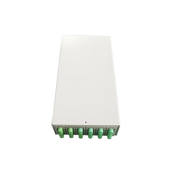
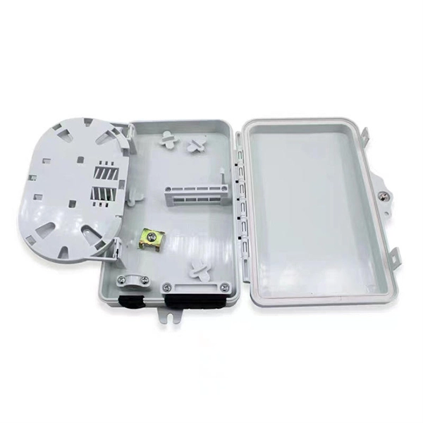
How to connect the fiber optic box and the terminal box
Secure the box with screws (ensure depth ≥40mm). Run incoming fiber cable through the box's entry port. Connect ONT to socket with. Learn how to install a fiber optic termination box step-by-step for FTTH projects. Covers mounting, splicing, routing, labeling, and testing for indoor/outdoor use. Thus, a fiber termination box is used to terminate the optical fiber. Installing a fiber wall socket (also called an FTTH outlet or optical termination point) is critical for maximizing your fiber internet speed and reliability. Post-installation optimization matters —proper router placement, firmware updates, and network security configuration maximize your fiber internet investment.