-

Optical fiber cable optical attenuation of more than 30
Attenuation makes signals weaker in fiber optic cables. Check your optical transceiver's specs often. This keeps the signal. Fiber loss, also called fiber optic attenuation or attenuation loss, refers to the loss of signal between input and output. Losses can be introduced by various means such as intrinsic material absorption, scattering, bending, connector loss and more. As depicted below, the decibel, which is used to compare two power levels in dBm, can be defined as the ratio of the optical power P o at the fiber's output to the optical power P i at the fiber's input at a specific. To determine the power budget and power margin needed for fiber-optic connections, you need to understand how signal loss, attenuation, and dispersion affect transmission.
-
A single optical fiber uses a dual-core optical module
o In optical modules, "core" refers to the light-transmitting channel in the fiber. A 1-core module uses a single fiber core for data transmission, while a 2-core module uses two cores. They are easier to set up and give steady communication. A. Single fiber module also called BiDi transceiver or WDM module. BIDI module only has 1 port, wave filtering through the filter of module, and finished the transmitting of 1310nm optical signal. In today's communication field, single-core optical fibre and dual-core optical fibre are like remarkable stars, the powerful technology behind them and the disruptive impact on the communication industry deserve everyone's attention and discussion.
-
10 Gigabit Ethernet card optical module not connected to fiber optic cable
Troubleshooting SFP+ link issues in 10 GbE networks requires attention to module type, match of speed and wavelength, clean fiber connections, correct configuration, thermal management, and equipment compatibility. You can quickly resolve SFP+ Module connectivity issues by following a systematic optical transceivers troubleshooting process. Check for common connection problems, such as link failures or modules not recognized. Check compatibility between the optical module and switch Most switch brands have specific compatibility requirements. During network upgrades, many enterprise users encounter a common issue: after replacing 10G broadband lines or inserting 10G SFP+ optical modules, the switch still fails to operate at full 10G bandwidth or even fails to recognize the modules. We've listed the five most common ones. First of all, let's briefly recap what SFP and SFP+ stand for. SFPs – short for 'small form-factor pluggable' – are compact, hot-pluggable devices.
[PDF Version]
-
Optical fiber cables have high return loss
An fiber can have some finite return loss due to Rayleigh backscattering. This is exploited in the context of optical time-domain reflectometry, which is widely used for monitoring the status of fiber-optic links. Reflectance (which has also been called "back reflection" or optical return loss) of a connection is the amount of light that is reflected back up the fiber toward the source by light reflections off the interface of the polished end surface of the mated connectors and air. This is always measured in dB (decibels) and will be displayed as a negative number. the reflection above the fiber backscatter level, relative to the source pulse, is called reflectance. Optical return loss is given in units of dB and always a.
-
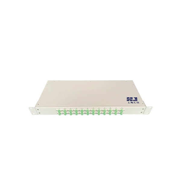
Optical cross-link fiber optic cable tail
A fiber optic pigtail is a pre-installed connector on one end of an optical cable and a length of exposed fiber at the other end. They are the bridge between fiber optic cables in the field and the equipment or patch panels that manage them. Get the wrong connector type, the wrong polish, or skip proper fusion splicing technique—and you're looking at elevated signal loss, increased back reflection, and a. ■ What is a fiber optic pigtail cable? A pigtail fiber indicates a short length of optical fiber cable that has a pigtail connector (for example, SC, FC, ST, LC, etc. ) fitted on one end and the other end undressed (for connection through fusion or splicing) to the main fiber optic cable.
-

How to measure the optical attenuation value of fiber optic patch cords
The primary tool for measuring attenuation in installed fiber is an Optical Time Domain Reflectometer, or OTDR. The most fundamental parameter for optical fiber is geometry, since the dimensions of the fiber determine its ability to be spliced and terminated to other fibers. The core diameter, cladding diameter and concentricity are the most important factors on how well one can connect or splice two fibers. In this tutorial, we'll take a look at the.