-
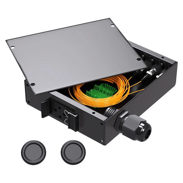
What are the components of an optical guide driver module
The optical module is usually composed of Transmitter Optical Subassembly (TOSA, containing a laser LD Chip), Receiver Optical Subassembly (ROSA, containing a photodetector PD Chip), a driving circuit, and an optical and electrical interface. Its schematic is shown in Figure 1. The internal structure of an optical module is complex but can be divided into several main parts. It is the core device for connecting communication equipment with optical fibers. Operating at the physical layer of the OSI model, optical modules are core devices in optical. As an important part of fiber-optic communication, an optical module is a photoelectric converter which converts electrical signals into optical signals and vice versa. Composition of Optical Modules The optical module, known as Optical Transceiver in. The optical module serves as a crucial component in optical fiber communication systems, operating at the physical layer, which is the lowest layer in the OSI model.
[PDF Version]
-
Wired Channel for Relay Protection
With the addition of a line tuner, the CCVT (used for potential input to the protective relay) can be used to couple the PLC signal to the power line. Protection systems are used to isolate faulted parts of the system, protect the electric system from instability, and minimize equipment damage. Directional distance and overcurrent schemes, interfaced with communication equipment, send and receive logic-based information between relay te minals to determine if the fault is external or internal to the. Important benefits include limiting tripping to faulted line section, high-speed simultaneous clearing for all internal line faults, preventing overtripping on external faults, and reducing transmission line and station damage. Applications of the concepts to accepted transmission line-protection schemes are also presented.
-

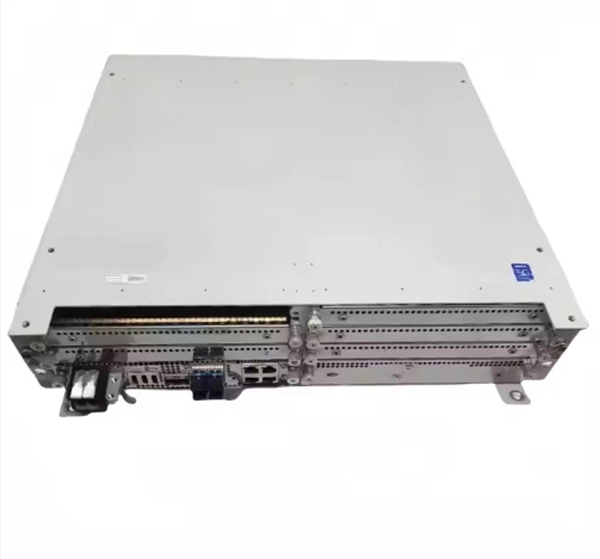
Circuit Breaker Relay Protection Equipment Model
Microprocessor-based solid-state digital protection relays now emulate the original devices, as well as providing types of protection and supervision impractical with electromechanical relays.OverviewIn, a protective relay is a device designed to trip a when a is detected. The first protective relays were electromagnetic devices, relying on coils operating on moving par. Electromechanical protective relays operate by either, or. Unlike switching type electromechanical with fixed and usually ill-defined operating voltage thresholds. Electromechanical relays can be classified into several different types as follows: "Armature"-type relays have a pivoted lever supported on a hinge or knife-edge pivot, which carries a moving contact. These relays may.
-
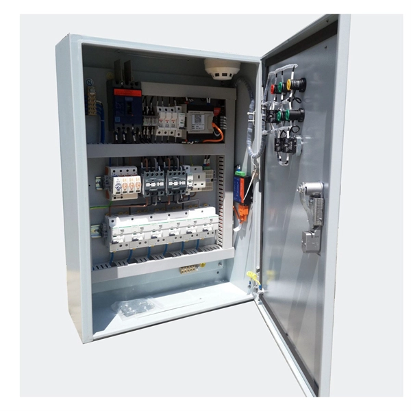
Requirements for Relay Protection Design
The IEEE standard for protection relays refers to a collection of guidelines developed by the Institute of Electrical and Electronics Engineers. This document provides recommendations, background and philosophy on relay protection that is not available in M07. They are intended to quickly identify a fault and isolate it so the balance of the system continue to run under normal conditions. For professionals working in utilities, industries, or renewable energy systems, understanding these standards is not optional—it is essential. This handbook covers the code of practice in protection circuitry including standard lead and device numbers, mode of connections at terminal strips, colour codes in multicore cables, dos and donts in execution.
-

Relay Protection Test Wiring Method
One approach to test the total protection system is to use primary injection techniques (see appendix H) that trigger protective relays and lockout relay, trip circuit breakers, and initiate annunciations and indications. If applicable, documentation is required detailing how verified protection segments overlap to ensure there is not a gap. The purpose of this Standard Work Practice (SWP) is to standardise and describe the method for testing of Ergon Energy protection relays for commissioning purposes. This SWP should be interpreted in conjunction with Standard for Substation Protection (V1. From a technician's perspective, master the unique skill of testing protection. When the transformer wiring type is Y/Y (Y0), the test wiring is very simple: when testing phase A, the tester IA is connected to the phase A of the high voltage side, and the tester IB is connected to the phase a of the low voltage side. After the neutral line of the high and low voltage sides is. Function: Use electronic components like transistors to perform switching. Applications: Frequency, undervoltage, and overcurrent protection.
[PDF Version]
-
Several characteristics of relay protection are
To provide effective and reliable protection to the power system, a protective relay must have the following essential functional characteristics: Selective, Fast, Stable, Reliability, Sensitivity, Simple Construction and Installation Mechanism, and Cost-effective. A protective relay is an electrical switch which can automatically operate when a fault or any other abnormal conditions occur in the electrical system. It sends a signal to turn on the alarm or indicator or trip a circuit breaker to separate the faulty part from the healthy section. : 4 The first protective relays were electromagnetic devices, relying on coils operating on moving parts to provide detection of abnormal operating conditions such as. A protective relay is an intelligent electrical device designed to detect faults in power systems and initiate corrective actions such as tripping a circuit breaker. PSM – Plug Setting Multiplier (Current Setting Multiplier) What is PSM? 2).
[PDF Version]
-

Analysis of the Four Characteristics of Relay Protection
The article first analyzes the role, composition, requirements of relay protection, and then analyzes the fault analysis of power system protection and treatment measures; the final analyzes the question of the relay protection substation operation. (1) Selectivity: refers to that when the Electrical fault occurs, the relay protection device acts and only removes the fault element. Minimize the scope of power outages as much as possible to continue the operation of non faulty parts of the system. Divide into main protection and backup. To provide effective and reliable protection to the power system, a protective relay must have the following essential functional characteristics: Selective, Fast, Stable, Reliability, Sensitivity, Simple Construction and Installation Mechanism, and Cost-effective. These are some essentially. Protective Relays - Technical Seminar Nov 2016 - Copyright: IEEE 2 Abstract: Protective relays and devices have been developed over 100 years ago to provide “lastline”of defense for the electrical systems. Therefore, the whole system has gone down, even though many circuit breakers have remained closed.
[PDF Version]
-

Is selling relay protection a good business opportunity
Growing power demand, an emergent market for intelligent controllers and Increasing Demand for Electronic Devices are some of the opportunities in the global protection relay market. Pro Market Reports (PMR) excels in delivering thorough market research and detailed market analysis across a variety of industries. Firstly, the increasing demand for reliable and uninterrupted power supply, especially in emerging economies undergoing rapid industrialization and urbanization, is propelling the need for. The Global Protective Relay Market is poised for steady expansion, with a forecasted value of USD 4. 9 billion in 2024, expected to reach USD 7. Protective relays are essential components of modern power systems. A protective relay is a relay, which is considered to trip a circuit breaker when any fault is identified.
-
Six-Column Relay Protection Tester
Specifically designed for settings-based protection testing with a high degree of automation, our modular software Test Universe offers numerous functions and application-optimized test modules that save yo.
-
Is relay protection a high-voltage system
Protective relaying is the backbone of fault detection and system isolation in high voltage (HV) power networks. As transmission systems grow increasingly complex with integration of renewables and smart technologies, the design, configuration, and application of protective relays have become more. The article provides an overview of protective relaying principles and their applications for high-voltage power system components. It covers the protection methods for generators, transformers, buses, and transmission lines using various relay types to detect and isolate faults efficiently. The relays are in round glass cases. This prevents damage to equipment, reduces downtime, and safeguards.