-
Distance from distribution box to cable
Where communication cables attach to a building near service conductors, a minimum vertical separation of 12 inches is standard practice to prevent accidental contact between the two systems. These rules exist to prevent electrocution, fire, and equipment damage. The NEC, published by the National Fire Protection Association, is the baseline safety standard for electrical installations across all 50 states, though local jurisdictions often adopt it with modifications. 1 As of early. Phase-to-ground voltage refers to the voltage difference between an energized conductor and the ground, while phase-to-phase system voltage represents the voltage difference between two energized conductors. A conduit body is a removable-cover section of a conduit system that provides access at. Governed by NEC 110. The core components of this standard involve the Depth of working space, which varies based on the system's. The meter is a combination system that includes a service disconnect. Whether it is residential buildings, commercial facilities or industrial sites, the.
[PDF Version]
-
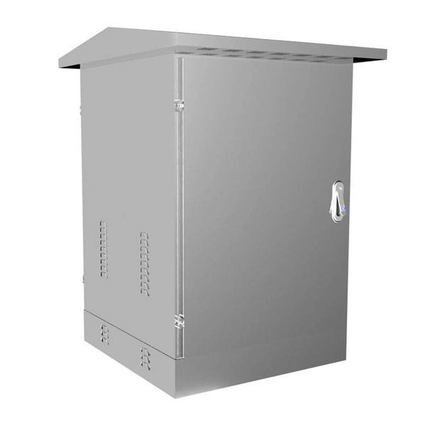
Distance between upper and lower rails of the distribution box
Vertical distance between adjacent cable trays, measured from the bottom of upper tray to the bottom of the lower tray, shall be at least 400 mm. To avoid damage during cable laying, cable trays and accessories shall have no scales, abrasive, rough surfaces or cutting edges. This damage is often not apparent until post-installation cable testing. This is an inefficient and expensive way to do an. It is fairly well understood that if an assembly short-circuit current rating above 10,000 amperes is desired, a Power Distribution Block or a Terminal Block with a high short-circuit current rating must be utilized. However, there is great confusion concerning the spacing requirements of these. Conductor damage during installation is one consequence of undersizing junction and pull boxes. The size of the electrical gap directly affects the safety.
[PDF Version]
-

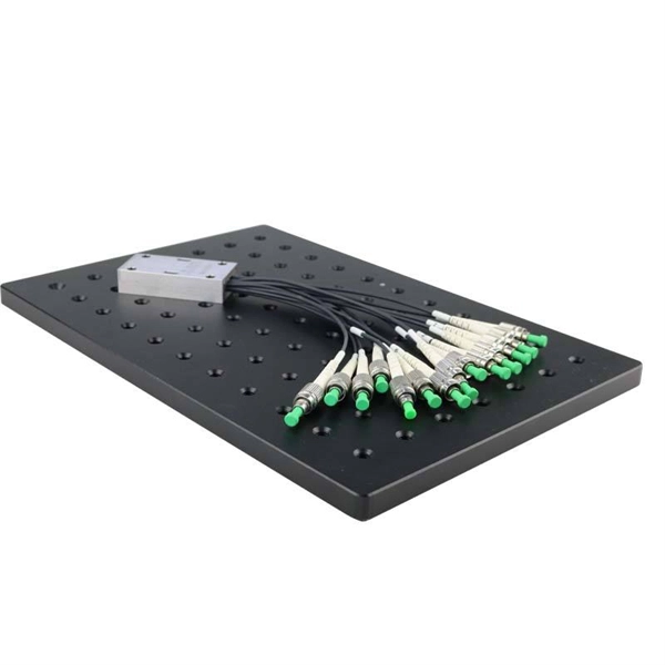
Extending Fiber Optic Communication Distance
Optical amplifiers, such as Erbium-Doped Fiber Amplifiers (EDFAs), are commonly used in long-distance, high-capacity networks (such as submarine cables) to extend transmission distances. Fiber optic cable transmission distance is determined by two primary physical factors that affect signal quality as light travels through the fiber medium. The greater the distance, the greater. Bending: The fiber is squeezed, and other reasons cause bending, which causes part of the light to be lost due to scattering, resulting in attenuation. Refractive index: uneven refractive index of the. If you get your hands on a Pre-terminated Fiber Optic Assembly and a couple of Media Converters, you're only a few steps away from extending your small wifi network more than 250 feet. Check out the summary of what we're about to explain below. Where possible, opt for a.
[PDF Version]
-

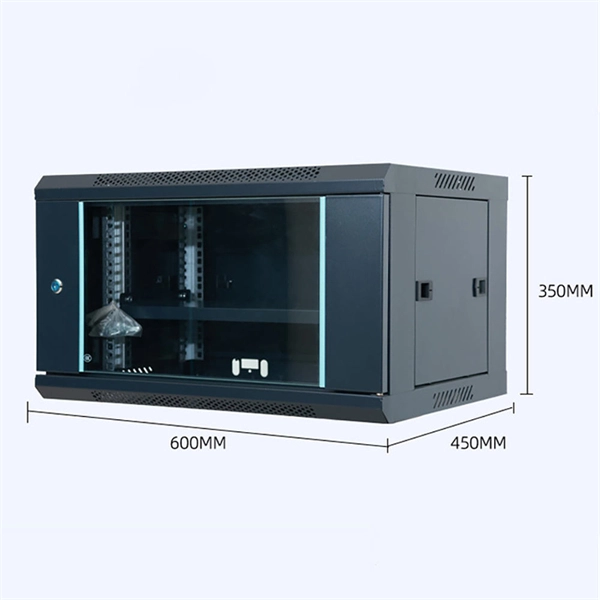
How much distance should there be between the cable tray and the side support
For horizontal sections where cable trays are laid out in a straight line, the typical support span (distance between supports) should range from 1. This range allows for easy access and efficient maintenance. The NEC requires that cable trays must be supported by members at an interval specified by the cable tray manufacturer, but not more than 5 feet for horizontal runs to support the weight of the cables and other loads. According to the regulations under NEC 392. 10 (B) (1), the smallest size single conductor allowed to be installed in a cable tray is 1/0 AWG. For the installation of single conductor cables sized 1/0 AWG to 4/0 AWG in industrial establishments, the NEC specifies the maximum allowable rung spacing for the cable. Unlike a simple wire trough, which is typically a covered channel for shorter runs, cable trays provide a comprehensive support system for complex wiring paths over long distances. A well-planned cable tray installation not only organizes conductors but also provides protection and makes future.
[PDF Version]
-
The single-mode fiber optic distance is 300 meters
A: For most applications, the maximum distance of a single-mode cable is around 160 kilometers. Q: How far can multimode fiber go? A: It varies with the data speed and fiber type. Due to the small core, only one optical mode is allowed to be transmitted. This characteristic enables single-mode fibers to transmit signals over long distances with low mode dispersion (mode. Fiber optic cable can be run anywhere from 300 meters up to 80 kilometers (roughly 50 miles) depending on the cable type, transceiver used, and network standard. Simply plug the cable to any fiber port on the device and high speed fiber optic link between two long distance locations can be generated by. Single-mode fiber (SMF): Uses a single light path, enabling it to transmit data over longer distances with less signal loss.
-
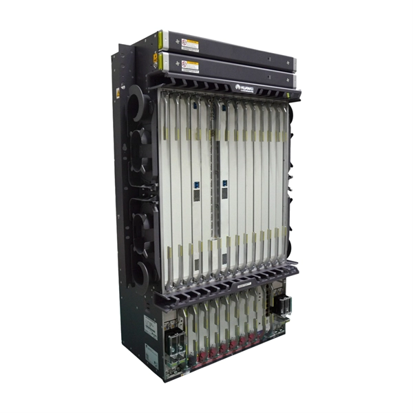
Fiber optic cable to ground distance monitoring
Enter Distributed Fiber Optic Sensing (DFOS), a transformative technology that leverages existing fiber optic cables to provide continuous, real-time monitoring over long distances. FOGrid: FEBUS Optics' cable monitoring solution applied to an offshore wind turbine farm FOGrid is FEBUS Optics' comprehensive and easy to deploy solution to ensure a continuous real-time monitoring of the integrity of buried or overhead cables, whether offshore or onshore. Traditional monitoring approaches rely on discrete point sensors—inclinometers, extensometers, and survey prisms—that measure conditions only at specific. Underground cable monitoring is crucial for maintaining reliability and preventing failures caused by environmental and mechanical threats. By detecting issues early, it enables proactive maintenance, reducing the risk of service disruptions and costly repairs. Advanced technologies like.
[PDF Version]