-
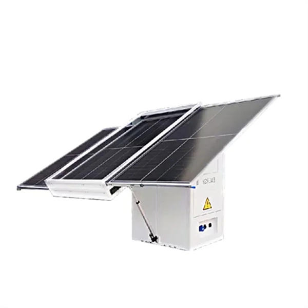
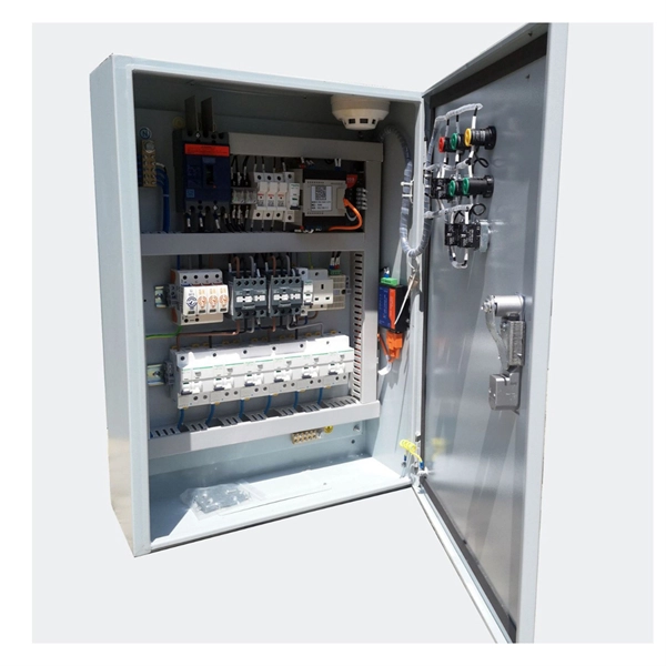
Does the elevator machine room necessarily need a separate electrical control box
Each car, machine room and hoistway pit must have separate dedicated branch circuits for lighting, receptacles and HVAC, with car and machine-room lighting exempt from GFCI while required for receptacles. Overcurrent devices and disconnects must be located in machine or control spaces, be lockable. Provide a legally constructed and enclosed control room, adequately lighted, and conditioned to maintain temperature between 60° to 90° Fahrenheit, relative humidity is not to exceed 90% non-condensing. Control room must be of adequate size to provide clearances around and between equipment as. Main Power Circuit: Typically, a 240VAC, 30 Amp dedicated line with 10/3 copper wiring (including a dedicated neutral and ground) serves the elevator motor and controls. This is always an isolated circuit, never shared. Typically, for residential elevators, a machine room will be located on the lowest landing as close as possible to the elevator hoistway. These systems eliminate the need for a separate room to house hydraulic pumps, control panels, etc. However, they do present some challenges.
[PDF Version]
-
Complete Guide to Cutting Inner Bends of Cable Trays
This guide explains how to make 90° bends, vertical bends, tees, and offsets in wire mesh cable trays safely and professionally. Horizontal 90° Bend (Flat Bend) 2. Cross Bend (4-Way. OTHER THAN 90 ̊ JUNCTIONS Use this guide to learn the most effective installation practices when installing Cablofil tray. Each example of bends and tee's clearly illustrate proper tray cutting combined with recommended usage of Cablofil accessories. Oglaend System manufacture and deliver Multidiscipline modular bolted support systems, cable trays, cable ladders and accessories for complete installation and containment of Instrument, Electrical, Telecom, HVAC and Piping. Hubbell Wiring Device-Kellems and Hubbell Premise Wiring are divisions of Hubbell Incorporated, a U. headquartered manufacturer with over 130 years of supplying solutions for the electrical and data markets.
[PDF Version]
-
The function of the light guide bar light source module
Through the light diffusion structures on the incidence surface of the light guide bar and the full-reflection action of the light inside the light guide bar, the light guide bar can provide illumination with uniform brightness; and moreover, the utilization rate of. Through the light diffusion structures on the incidence surface of the light guide bar and the full-reflection action of the light inside the light guide bar, the light guide bar can provide illumination with uniform brightness; and moreover, the utilization rate of. The invention discloses a light guide bar and a light source module adopting the same. On a cross-sectional plane of the light guiding bar, there is a first line interval on the upper surface. A second line interval, a third line interval and a. Modern light guides are used for the transportation of light signals from a circuit-board-mounted LED via a particular route to a defined light-emitting surface, with minimal loss and blurring effect. They are used to illuminate areas that are too small or too hazardous to permit the installation of a light bulb.
[PDF Version]
-

A Comprehensive Guide to Seismic Supports for Palestinian Bridge Structures
Hatem Alwahsh f• Dynamic analysis: the analysis shall be based on an appropriate ground motion representation and shall be performed using accepted principles of dynamics. The main methods of dyn.
-
Optical Module Base Design
Optical module usually consists of a transmitter assembly (TOSA, containing a laser LD chip), a receiver assembly (ROSA, containing a photodetector PD chip), a driver circuit, an optoelectronic interface, a heat sink (some models), a housing, a pull ring and so on. Integrated circuits and reference designs help you create a smaller and faster optical module design used in high-bandwidth data communication applications. Whether you are creating a 100-Gbps or 400-Gbps, small form-factor pluggable (SFP) module, SFP+ transceiver, XFP module, CFP, X2/XENPAK module. Designing and producing these complex PCBs presents formidable challenges, requiring a convergence of disciplines—from high-frequency signal integrity and advanced thermal management to micron-level mechanical precision. These three laser diodes are described in more detail. contact us product page Copyright © 2024 MVSLINK. Critical Metrics: Signal integrity (insertion loss, return loss) and thermal management are the two.
[PDF Version]
-

Principles and Product Design of Optical Fiber Communication
Optical Fiber Communication (OFC) revolutionizes modern telecommunications, enabling rapid data transfer across long distances with minimal signal loss. This comprehensive review explores OFC's historical evolution, core principles, components, and versatile applications. Kanade Department of Electronic-Science, P. College of ASC, Pravaranagar, India fPublished. The digital communication techniques discussed so far have led to the advancement in the study of both Optical and Satellite communications. Light acts as a carrier wave and can be modulated to carry information. Higher bandwidth (extremely high data transfer rate).
-
WDM Fiber Optic Communication System Design
This lesson demonstrates the basic features of a typical WDM optical communication system and shows the basic design steps with OptiSystem. The performance of the system will be shown and compared. In fiber-optic communications, wavelength-division multiplexing (WDM) is a technology which multiplexes a number of optical carrier signals onto a single optical fiber by using different wavelengths (i. Single mode fiber is favored over Multimode fiber for long-distance communication. Firstly, the WDM optical. While fiberoptic technology resulted in a significant increase in a network's "bandwidth," or the amount of information that the network could send, tbe creation of the Internet resulted in an even greater demand for bandwidth. As demand for network capacity increased, service providers exhausted.
-
Requirements for Relay Protection Design
The IEEE standard for protection relays refers to a collection of guidelines developed by the Institute of Electrical and Electronics Engineers. This document provides recommendations, background and philosophy on relay protection that is not available in M07. They are intended to quickly identify a fault and isolate it so the balance of the system continue to run under normal conditions. For professionals working in utilities, industries, or renewable energy systems, understanding these standards is not optional—it is essential. This handbook covers the code of practice in protection circuitry including standard lead and device numbers, mode of connections at terminal strips, colour codes in multicore cables, dos and donts in execution.
-

Emergency Circuit Design for Distribution Boxes
Size emergency and standby circuits with NEC 700/701, IEC 60364-5-56, UPS/generator transfer paths, and real voltage-drop examples. On a recent plan review, the riser looked clean: NEC 700 emergency lighting, a listed transfer switch, copper conductors, and breakers sized. Emergency and standby power systems are designed to provide an alternate source of power if the normal source of power, typically the electric utility service, should fail. Reliability of these types of systems is critical and good design practices are essential. Classification of Emergency and. Emergency system circuits supply power to critical life safety loads such as emergency lighting, fire alarm systems, fire pumps, smoke control systems, and essential communication and control circuits. Correct wiring design for emergency system circuits is essential to maintain power integrity. The National Electrical Code (NEC) Section 700. Under no. Another is to limit what qualifies as an “emergency load,” so the emergency system powers only what is needed to save human life (Fig.
[PDF Version]
-
What are the components of an optical guide driver module
The optical module is usually composed of Transmitter Optical Subassembly (TOSA, containing a laser LD Chip), Receiver Optical Subassembly (ROSA, containing a photodetector PD Chip), a driving circuit, and an optical and electrical interface. Its schematic is shown in Figure 1. The internal structure of an optical module is complex but can be divided into several main parts. It is the core device for connecting communication equipment with optical fibers. Operating at the physical layer of the OSI model, optical modules are core devices in optical. As an important part of fiber-optic communication, an optical module is a photoelectric converter which converts electrical signals into optical signals and vice versa. Composition of Optical Modules The optical module, known as Optical Transceiver in. The optical module serves as a crucial component in optical fiber communication systems, operating at the physical layer, which is the lowest layer in the OSI model.
[PDF Version]