-
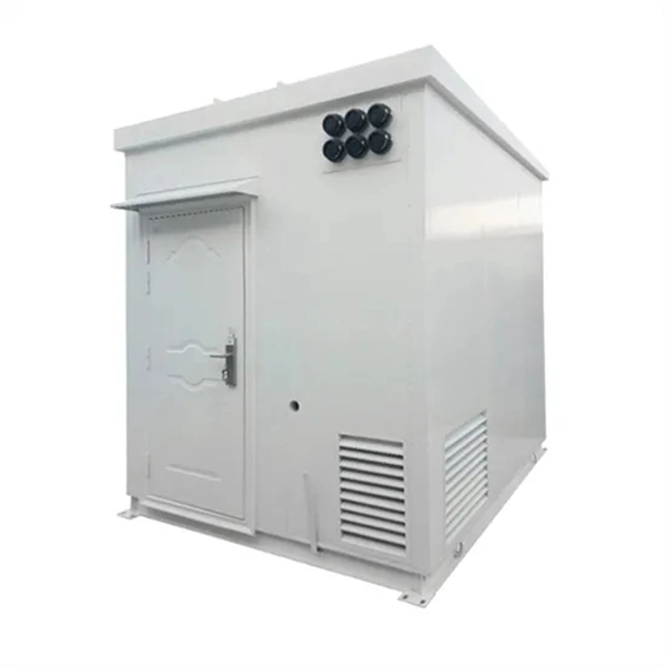
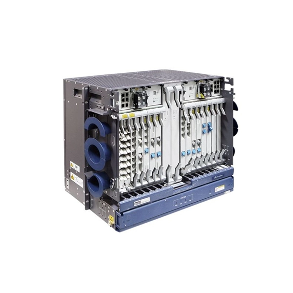
Installation Solution for Integrated Energy Cabinets in Denmark IP67 Standard
IP67-rated pack design, multi-level fire protection; High-reliability system architecture with electrical redundancy protection. Hermetic aluminum electrical distribution cabinets – professional solutions designed for installation and protection of electrical equipment, switches, meters, protection and control components. Meeting IP67 requirements ensures waterproof enclosures provide security for housing internal components in wet environments. With a variety of sizes available in aluminum or. IP67-rated enclosures aren't just metal boxes; they're engineered ecosystems protecting sensitive electronics from particulate ingress (IEC 60529) and temporary submersion. at 24 VDC) Safety functions - Integrated Special versions - Watertight enclosure Detection - Access control Operating Range (m). With the PDP67 modules, Pilz offers solutions for decentralised applications directly in the field. The decentralised modules optimise installation and wiring work.
[PDF Version]
-
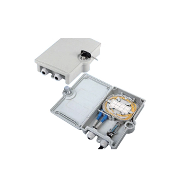
Installation of the distribution box frame
Learn how to install a distribution box safely and correctly. It takes the incoming power and safely distributes it to different circuits. Whether you are an electrical contractor or a construction brigade, knowing how to properly and safely install distribution boxes is the basis of ensuring the safe operation of the entire system. Covers wiring, placement, standards, and expert tips for a compliant setup. This manual is for electronic distribution only and is designed to provide you with the most current information on the Los Angeles Department of Water and Power's (Department) service equipment and installation requirements. The I F s currently PreConfigur to support the system layout as shown in Figure 1, page 1. The allowable size of a ch des the.
-

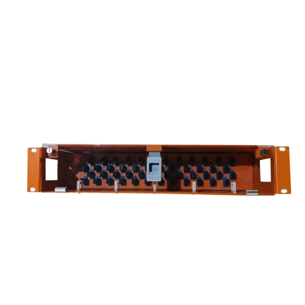
Switch cabinet busbar installation
In North America, follow UL 891 construction and NEC Article 408 installation practices: use listed/approved hardware, lugs, or tap-off provisions intended for the bus. The matrix below helps engineers finalize material, arrangement, plating/insulation, and verification. The GRL busbar system makes distribution cabinet installation fast, flexible, and neat. At this stage, the supports have been installed in accordance with the installation plan. Ever wondered how busbars, the unsung heroes of electrical distribution, are processed and installed? This article delves into the intricate steps of busbar selection, preparation, and installation, ensuring efficient and safe power distribution. The application of these rules means strict compliance, not only with applicable regulations and standards, but also with manufacturers'. Bus bars play a crucial role in electrical distribution systems by providing a reliable and efficient way to conduct electricity within electrical panels.
[PDF Version]
-
Requirements for Cable Trench and Cable Tray Installation
This article provides a comprehensive framework that governs various aspects of cable tray installations, including the types of cables that are deemed acceptable for use, requirements for grounding and bonding, and stipulations regarding tray fill capacity. Additionally, it addresses critical. NEC Article 392 outlines the key rules for installing and maintaining industrial cable tray systems. These systems, made from metal or plastic, are open structures designed to support electrical conductors, ensuring proper organization and safety. This installation is for underground services from 2001 amps to 4000 amps. The following pages address the 2014 National Electrical Code® requirements for cable tray systems as well as design. Cable tray systems provide a safe, organized, and flexible method for supporting insulated conductors and cables in commercial and industrial electrical installations.
[PDF Version]
-
Cable tray connector installation price
Cable tray pricing depends on materials, coatings, size, supplier margins, and order quantity —plus hidden costs like shipping and installation. Cable tray installation cost per meter varies by specifications; GangLong Fiberglass offers kits for raised floor system and facility needs. This guide breaks down everything buyers need to know, from price trends to cost-saving tips. The average cable tray price per meter ranges from $2 to. A cable tray system is used to support insulated electrical cables used for power distribution, control, and communication. A 2026 Comparison vs. The majority of individuals will consider the cost of the components. That number matters, but it's rarely the one that decides whether a project stays within budget. The real cost shows up later, during installation, during upgrades, and during the first few years of operation.
[PDF Version]
-
Installation height of the three-level electrical distribution box on the construction site
The proper installation of a distribution box involves placing it at the right height to ensure safety and convenience. However, the key to. The dimension for height of working space for equipment operating at 600 volts (V), nominal, or less to ground and likely to require examination, adjustment, servicing or maintenance while energized shall comply with the 110. The work space shall be clear and extend from the grade, floor. Dedicated Space: Dedicated electrical space is required for panel from the floor to a height of 1. This height also safeguards the box from potential. Due to the long time interval between the embedding of the box and the installation and wiring of the box panel, the box shall be disassembled with the box cover (door) and the panel first, and marked for storage, so as to prevent the electrical components and the box cover (door) from damage or. This subpart addresses electrical safety requirements that are necessary for the practical safeguarding of employees involved in construction work and is divided into four major divisions and applicable definitions as follows: (a) Installation safety requirements. Installation safety requirements.
[PDF Version]
-
Standard installation height for household electrical distribution boxes
The proper installation of a distribution box involves placing it at the right height to ensure safety and convenience. This height also safeguards the box from potential. Check for proper IP/NEMA ratings and material quality. Ensure safe placement: install in dry, accessible areas with good ventilation and at appropriate height (typically ~1. Practice good wiring: secure grounding, neat cable management, proper insulation, and correct wire gauge and breaker. The most common question regarding electrical panel installation involves the maximum height allowed for the device. The National Electrical Code (NEC) specifies that the center of the grip of the operating handle of the highest circuit breaker must not be located more than 6 feet 7 inches (2. Ground-mounted foundations should be 50 to 100 mm above ground level.
-
Installation height of shaft electrical distribution box
The proper installation of a distribution box involves placing it at the right height to ensure safety and convenience. Check for proper IP/NEMA ratings and material quality. Ensure safe placement: install in dry, accessible areas with good ventilation and at appropriate height (typically ~1. Article 314 applies to: These. FIRE ALARM VISUAL ONLY DEVICE OR A COMBINATION AUDIBLE AND 80" TO BOTTOM OF DEVICE OR NOT MORE THAN 96" TO TOP. 54" TO DIAL CENTER (NON-ACCESSIBLE). Ground-mounted foundations should be 50 to 100 mm above ground level.
-
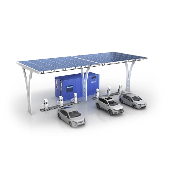
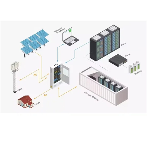
Photovoltaic Power Generation Module Installation Method
This article walks you through the basics of PV system installation, focusing on the practical steps from mounting modules to connecting the inverter to the electrical grid, and emphasizes the importance of ongoing maintenance to optimize system performance. (hereinafter referred to as LONGi). Please abide by all safety precautions in this guide and local regulations. •Installation of. Installing photovoltaic (PV) systems is a key stride toward embracing renewable energy, which is crucial for reducing carbon footprints and fostering sustainable energy use. Starting with a detailed site assessment to evaluate solar potential and optimal setup, the process ensures efficiency and. Protective earth grounding of the individual photovoltaic modules is achieved by securing the modules to the SRS mounting system. This guide provides detailed instructions for the proper application of SIRIUS PV modules.
[PDF Version]